Toyota Camry (XV70): Removal
REMOVAL
CAUTION / NOTICE / HINT
The necessary procedures (adjustment, calibration, initialization, or registration) that must be performed after parts are removed and installed, or replaced during front frame assembly removal/installation are shown below.
Necessary Procedures After Parts Removed/Installed/Replaced|
Replaced Part or Performed Procedure |
Necessary Procedure | Effect/Inoperative Function when Necessary Procedure not Performed |
Link |
|---|---|---|---|
|
*1: w/ Smart Key System
*2: w/o Smart Key System *3: When the ECM is replaced with a new one, reset memory is unnecessary. | |||
|
Battery terminal is disconnected/reconnected |
Perform steering sensor zero point calibration |
Lane Tracing Assist System |
|
|
Pre-collision system | |||
|
Memorize steering angle neutral point |
Parking Assist Monitor System |
| |
|
Panoramic view monitor system |
| ||
|
Replacement of ECM | Vehicle Identification Number (VIN) registration |
MIL comes on | for A25A-FKS:
for 2GR-FKS:
|
|
ECU communication ID registration (Immobiliser system) |
Engine start function |
w/ Smart Key System: w/o Smart Key System:
| |
| Inspection After Repair |
| for A25A-FKS:
for 2GR-FKS:
|
|
Replacement of automatic transaxle assembly |
|
| for UB80E Initialization:
for UB80E Registration:
for UA80E Initialization:
for UA80E Registration:
for UB80F Initialization:
for UB80F Registration:
|
|
Replacement of ECM (If possible, read the transaxle compensation code from the previous ECM) |
| ||
| Replacement of ECM (If impossible, read the transaxle compensation code from the previous ECM) |
| ||
| Automatic transaxle fluid |
ATF thermal degradation estimate reset |
The value of the Data List item "ATF Thermal Degradation Estimate" is not estimated correctly. |
for UB80E: for UA80E:
for UB80F:
|
|
Replacement of ECM*1 | Code registration (Smart key System (for Start Function) |
|
|
|
Replacement of ECM*2 | Code registration (Immobiliser system (w/o Smart Key System)) |
|
|
|
Front wheel alignment adjustment |
|
| w/ Electric Parking Brake System: w/o Electric Parking Brake System: |
|
Suspension, tires, etc. (The vehicle height changes because of suspension or tire replacement) |
Rear television camera assembly optical axis (Back camera position setting) |
Parking assist monitor system |
for Initialization: for Calibration:
|
| Panoramic view monitor system |
for Initialization: for Calibration:
| |
|
Rack and pinion power steering gear assembly |
|
|
|
PROCEDURE
1. REMOVE ENGINE ASSEMBLY WITH TRANSAXLE
for A25A-FKS: Click here
.gif)
for 2GR-FKS: Click here
2. REMOVE FUEL DELIVERY GUARD (for A25A-FKS)
Click here
3. REMOVE FUEL PUMP PROTECTOR (for AWD)
Click here
4. INSTALL ENGINE HANGER
for A25A-FKS: Click here
for 2GR-FKS: Click here
5. REMOVE STEERING GEAR HEAT INSULATOR (for A25A-FKS)
Click here
6. DISCONNECT WIRE HARNESS
Click here
7. REMOVE FRONT FRAME ASSEMBLY
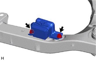
| (a) Remove the 3 nuts and separate the front engine mounting insulator from the front frame assembly. |
|
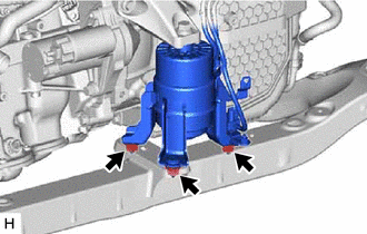
| (b) Remove the 4 nuts and separate the rear engine mounting insulator from the front frame assembly. |
|
8. REMOVE FRONT STABILIZER BAR WITH BRACKET
for A25A-FKS: Click here
for 2GR-FKS: Click here
9. REMOVE RACK AND PINION POWER STEERING GEAR ASSEMBLY
Click here
10. REMOVE FRONT LOWER NO. 1 SUSPENSION ARM SUB-ASSEMBLY LH
| (a) Remove the 3 bolts, nut and front lower No. 1 suspension arm sub-assembly LH from the front frame assembly. NOTICE: Because the nut has its own stopper, do not turn the nut. Loosen the bolt with the nut secured. |
|
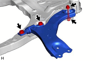
(b) Remove the front lower arm bushing stopper from the front lower No. 1 suspension arm sub-assembly.
11. REMOVE FRONT LOWER NO. 1 SUSPENSION ARM SUB-ASSEMBLY RH
HINT:
Perform the same procedure as for the LH side.
12. REMOVE NO. 2 EXHAUST PIPE SUPPORT BRACKET
| (a) Remove the 2 bolts and No. 2 exhaust pipe support bracket from the front frame assembly. |
|
13. REMOVE FRONT SUSPENSION MEMBER DYNAMIC DAMPER
| (a) Remove the 2 bolts and front suspension member dynamic damper from the front frame assembly. |
|
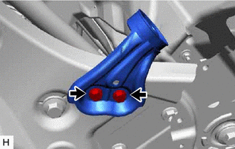
14. REMOVE FRONT SUSPENSION MEMBER BODY MOUNTING FRONT STOPPER
(a) Remove the 2 front suspension member body mounting front stoppers from the front frame assembly.
15. REMOVE FRONT SUSPENSION MEMBER BODY MOUNTING REAR STOPPER
(a) Remove the 2 front suspension member body mounting rear stoppers from the front frame assembly.
16. REMOVE FRONT SUSPENSION MEMBER BODY MOUNTING FRONT CUSHION (for LH Side)
| (a) Using a chisel and hammer, kink the flange of the front suspension member body mounting front cushion as shown in the illustration. |
|

(b) Apply lubricant to the contact surfaces of the front suspension member body mounting front cushion.
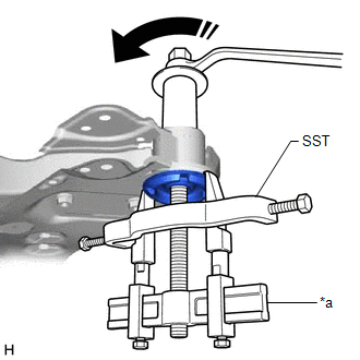
| (c) Install SST as shown in the illustration. SST: 09830-10010 09830-01010 09830-01040 09830-01050 SST: 09950-40011 09951-04020 09952-04010 09954-04010 09955-04011 09958-04011 NOTICE: Apply molybdenum grease to the threads and tip of the SST center bolt before use. |
|
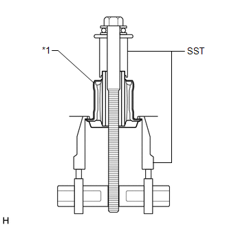
(d) Turn the SST center bolt as shown in the illustration to create a clearance between the front suspension member body mounting front cushion and the front frame assembly.
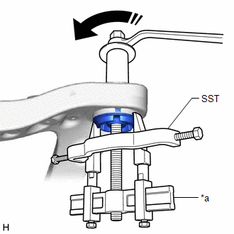
|
*a | Hold |
.png) |
Turn |
(e) While applying lubricant to the front suspension member body mounting front cushion through the clearance, gradually remove the front suspension member body mounting front cushion.
NOTICE:
- Tighten SST slowly and evenly.
- Be careful as the mounting cushion may fly out.
- The mounting cushion cannot be reused.
17. REMOVE FRONT SUSPENSION MEMBER BODY MOUNTING FRONT CUSHION (for RH Side)
HINT:
Perform the same procedure as for the LH side.
18. REMOVE FRONT SUSPENSION MEMBER BODY MOUNTING REAR CUSHION LH
| (a) Using a chisel and hammer, kink the flange of the front suspension member body mounting rear cushion LH as shown in the illustration. |
|

(b) Apply lubricant to the contact surfaces of the front suspension member body mounting rear cushion LH.
| (c) Install SST as shown in the illustration. SST: 09830-10010 09830-01010 09830-01040 09830-01050 SST: 09950-40011 09951-04020 09952-04010 09954-04010 09955-04011 09958-04011 NOTICE: Apply molybdenum grease to the threads and tip of the SST center bolt before use. |
|
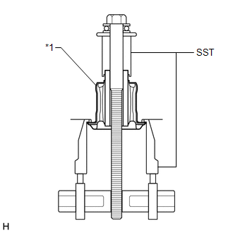
(d) Turn the SST center bolt as shown in the illustration to create a clearance between the front suspension member body mounting rear cushion LH and the front frame assembly.
|
*a | Hold |
|
|
Turn |
(e) While applying lubricant to the front suspension member body mounting rear cushion LH through the clearance, gradually remove the front suspension member body mounting rear cushion LH.
NOTICE:
- Tighten SST slowly and evenly.
- Be careful as the mounting cushion may fly out.
- The mounting cushion cannot be reused.
19. REMOVE FRONT SUSPENSION MEMBER BODY MOUNTING REAR CUSHION
HINT:
Perform the same procedure as for the front suspension member body mounting rear cushion LH.
20. REMOVE HOLE PLUG
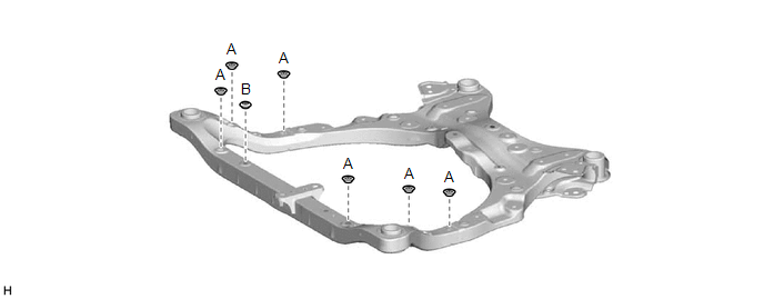
(a) Remove the 7 hole plugs from the front frame assembly.
HINT:
There are 2 different shapes of hole plug.
READ NEXT:
 Installation
INSTALLATION PROCEDURE 1. INSTALL HOLE PLUG
(a) Install the 7 hole plugs to the front frame assembly. HINT:
There are 2 different shapes of hole plug.
2. INSTALL FRONT SUSPENSION MEMBER BODY MO
Problem Symptoms Table
PROBLEM SYMPTOMS TABLE HINT: Use the table below to help determine the cause of problem symptoms. If multiple suspected areas are listed, the potential causes of the symptoms are listed in order of pr
SEE MORE:
Glossary Of Sae And Toyota Terms
GLOSSARY OF SAE AND TOYOTA TERMS This glossary lists all SAE-J1930 terms and abbreviations used in this manual in compliance with SAE recommendations, as well as their TOYOTA equivalents.
SAE Abbreviation SAE Term
TOYOTA Term ( )-Abbreviation
A/C Air Conditioning
Air Con
Brake System Control Module "A" System Internal Failure (C059704,C059746,C060B49,C061049,C13CF1C,C13D41C)
DESCRIPTION The following DTCs are stored when a malfunction occurs in the skid control ECU (brake actuator assembly).
DTC No. Detection Item
DTC Detection Condition Trouble Area
Memory Note
C059704 Brake System Control Module "A" System Internal Failure
Skid co
