Toyota Camry (XV70): Purge Valve
Components
COMPONENTS
ILLUSTRATION
|
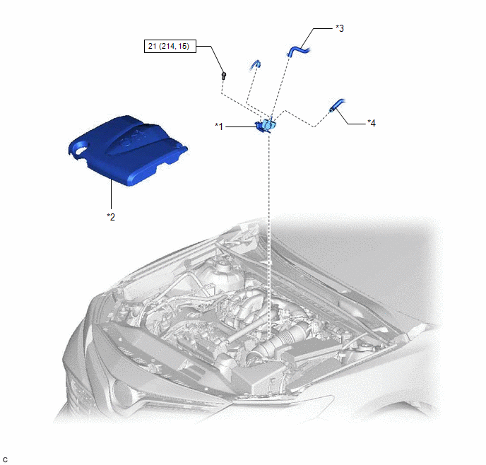
*1 | PURGE VALVE (PURGE VSV) |
*2 | V-BANK COVER SUB-ASSEMBLY |
|
*3 | FUEL VAPOR FEED HOSE |
*4 | NO. 1 FUEL VAPOR FEED HOSE |
.png) |
N*m (kgf*cm, ft.*lbf): Specified torque |
- | - |
Removal
REMOVAL
PROCEDURE
1. REMOVE V-BANK COVER SUB-ASSEMBLY
Click here
.gif)
2. REMOVE PURGE VALVE (PURGE VSV)
| (a) Disconnect the purge valve (purge VSV) connector. |
|
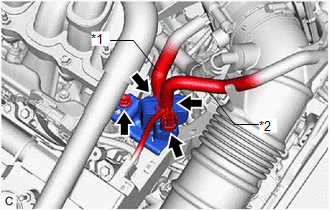
(b) Slide the clip and disconnect the fuel vapor feed hose from the purge valve (purge VSV).
(c) Disconnect the No. 1 fuel vapor feed hose from the purge valve (purge VSV).
(d) Remove the bolt and purge valve (purge VSV) from the intake air surge tank assembly.
Inspection
INSPECTION
PROCEDURE
1. INSPECT PURGE VALVE (PURGE VSV)
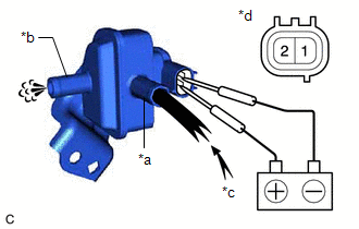
(a) Measure the resistance according to the value(s) in the table below.
Standard Resistance:
|
Tester Connection | Condition |
Specified Condition |
|---|---|---|
| 1 - 2 |
20°C (68°F) | 23 to 26 Ω |
If the result is not as specified, replace the purge valve (purge VSV).
| (b) Apply battery voltage between the terminals of the purge valve (purge VSV) and check that the following occurs when blowing air into the port (E). OK:
If the result is not as specified, replace the purge valve (purge VSV). |
|
Installation
INSTALLATION
PROCEDURE
1. INSTALL PURGE VALVE (PURGE VSV)
| (a) Install the purge valve (purge VSV) to the intake air surge tank assembly with the bolt. Torque: 21 N·m {214 kgf·cm, 15 ft·lbf} |
|
(b) Connect the No. 1 fuel vapor feed hose to the purge valve (purge VSV).
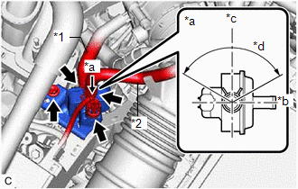
(c) Connect the fuel vapor feed hose to the purge valve (purge VSV) and slide the clip to secure it.
HINT:
Engage the clip within the area shown in the illustration.
(d) Connect the purge valve (purge VSV) connector.
2. INSTALL V-BANK COVER SUB-ASSEMBLY
Click here .gif)
READ NEXT:
 Accelerator Pedal
ComponentsCOMPONENTS ILLUSTRATION
*1 ACCELERATOR PEDAL
*2 ACCELERATOR PEDAL PAD
*3 ACCELERATOR PEDAL SENSOR ASSEMBLY
*4 NO. 1 INSTRUMENT PANEL UNDER COVER SUB-ASS
SEE MORE:
Data List / Active Test
DATA LIST / ACTIVE TEST DATA LIST HINT:
Using the Techstream to read the Data List allows the values or states of switches, sensors, actuators and other items to be read without removing any parts. This non-intrusive inspection can be very useful because intermittent conditions or signals may be di
Check Bus 2 Line for Short to +B
DESCRIPTION There may be a short circuit between one of the CAN bus lines and +B when there is no resistance between terminal 18 (CA4H) of the central gateway ECU (network gateway ECU) and terminal 16 (BAT) of the DLC3, or terminal 17 (CA4L) of the central gateway ECU (network gateway ECU) and termi
