Toyota Camry (XV70): Accelerator Pedal
Components
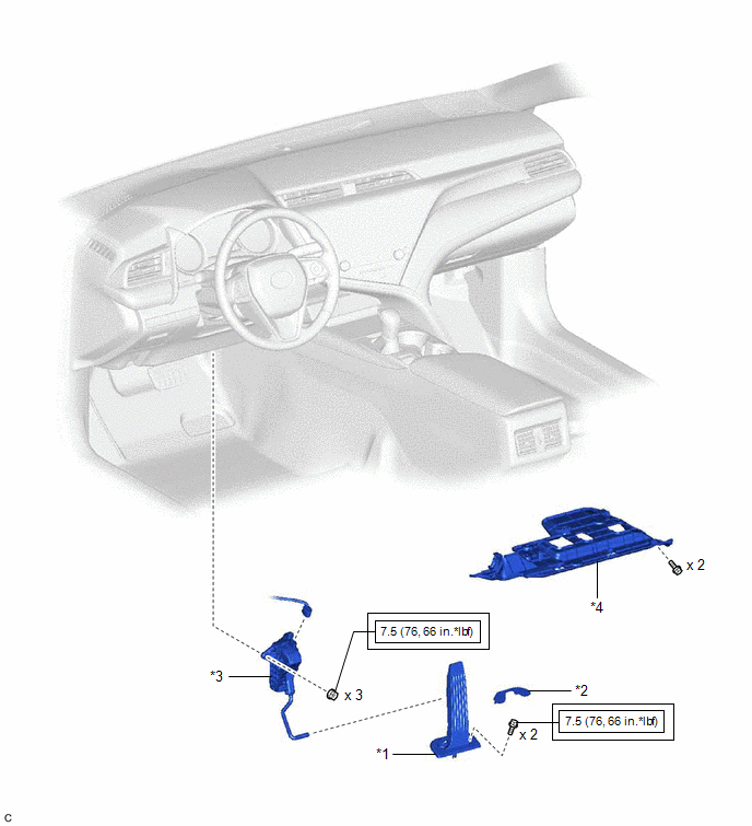
COMPONENTS
ILLUSTRATION
|
*1 | ACCELERATOR PEDAL |
*2 | ACCELERATOR PEDAL PAD |
|
*3 | ACCELERATOR PEDAL SENSOR ASSEMBLY |
*4 | NO. 1 INSTRUMENT PANEL UNDER COVER SUB-ASSEMBLY |
.png) |
Tightening torque for "Major areas involving basic vehicle performance such as moving/turning/stopping": N*m (kgf*cm, ft.*lbf) |
- | - |
On-vehicle Inspection
ON-VEHICLE INSPECTION
PROCEDURE
1. INSPECT ACCELERATOR PEDAL SENSOR ASSEMBLY
(a) Connect the Techstream to the DLC3.
(b) Turn the engine switch on (IG).
(c) Turn the Techstream on.
(d) Enter the following menus: Powertrain / Engine / Data List / Accelerator Position Sensor No. 1 Voltage and Accelerator Position Sensor No. 2 Voltage.
Powertrain > Engine > Data List|
Tester Display |
|---|
| Accelerator Position Sensor No.1 Voltage |
|
Accelerator Position Sensor No.2 Voltage |
(e) Read the values displayed on the Techstream.
Standard Voltage:
|
Techstream Display | Condition |
Specified Condition |
|---|---|---|
|
Accelerator Position Sensor No. 1 Voltage |
Accelerator pedal fully released |
0.5 to 1.1 V |
|
Accelerator pedal fully depressed |
2.6 to 4.5 V | |
|
Accelerator Position Sensor No. 2 Voltage |
Accelerator pedal fully released |
1.2 to 2.0 V |
|
Accelerator pedal fully depressed |
3.4 to 4.75 V |
If the result is not as specified, check the accelerator pedal sensor assembly, wire harness and ECM.
Removal
REMOVAL
PROCEDURE
1. REMOVE NO. 1 INSTRUMENT PANEL UNDER COVER SUB-ASSEMBLY
Click here
.gif)
2. REMOVE ACCELERATOR PEDAL(W/SENSOR) ROD ASSEMBLY
NOTICE:
- Avoid physical shock to the accelerator pedal sensor assembly.
- Do not disassemble the accelerator pedal sensor assembly.
- The accelerator pedal sensor assembly does not require lubrication.
- Do not apply oil or other lubricants to the accelerator pedal sensor assembly. If applied, the accelerator pedal sensor assembly must be replaced.
| (a) Disconnect the accelerator pedal sensor assembly connector. |
|
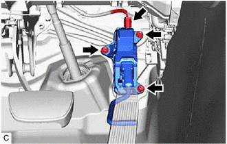
(b) Remove the 3 nuts and disconnect the rod of the accelerator pedal sensor assembly from the accelerator pedal to remove the accelerator pedal sensor assembly.
NOTICE:
If the accelerator pedal sensor assembly has been struck or dropped, replace it.
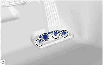
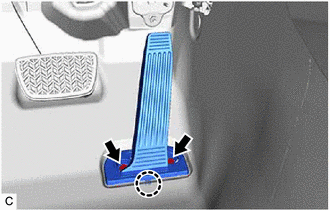
3. REMOVE ACCELERATOR PEDAL PAD
| (a) Disengage the 4 claws and remove the accelerator pedal pad from the accelerator pedal. |
|
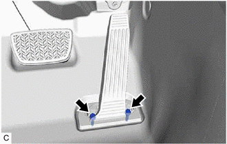
4. REMOVE ACCELERATOR PEDAL
| (a) Remove the 2 bolts. |
|
(b) Push the accelerator pedal in the direction indicated by the arrow (1) shown in the illustration to disengage the claw.
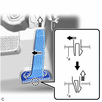
|
*a | Vehicle Body |
 |
Remove in this Direction (1) |
 |
Remove in this Direction (2) |
(c) Pull the accelerator pedal in the direction indicated by the arrow (2) shown in the illustration to remove it.
Installation
INSTALLATION
PROCEDURE
1. INSTALL ACCELERATOR PEDAL
| (a) Engage the claw to install the accelerator pedal. |
|
(b) Install the 2 bolts.
Torque:
7.5 N·m {76 kgf·cm, 66 in·lbf}
2. INSTALL ACCELERATOR PEDAL PAD
(a) Engage the 4 claws to install the accelerator pedal pad to the accelerator pedal.
3. INSTALL ACCELERATOR PEDAL(W/SENSOR) ROD ASSEMBLY
NOTICE:
- Avoid physical shock to the accelerator pedal sensor assembly.
- Do not disassemble the accelerator pedal sensor assembly.
- This accelerator pedal sensor assembly does not require lubrication.
- Do not apply oil or other lubricants to the accelerator pedal sensor assembly. If applied, the accelerator pedal sensor assembly must be replaced.
(a) Connect the rod of the accelerator pedal sensor assembly to the accelerator pedal and install the accelerator pedal sensor assembly with the 3 nuts.
Torque:
7.5 N·m {76 kgf·cm, 66 in·lbf}
(b) Connect the accelerator pedal sensor assembly connector.
4. INSTALL NO. 1 INSTRUMENT PANEL UNDER COVER SUB-ASSEMBLY
Click here
.gif)
READ NEXT:
 Components
COMPONENTS ILLUSTRATION
*1 FRONT ENGINE MOUNTING INSULATOR
*2 NO. 1 ENGINE UNDER COVER
*3 REAR ENGINE UNDER COVER LH
*4 V-BANK COVER SUB-ASSEMBLY
*5 VAC
On-vehicle Inspection
ON-VEHICLE INSPECTION CAUTION / NOTICE / HINT
HINT: Refer to Problem Symptoms Table. Click here
PROCEDURE
1. REMOVE FRONT WHEEL OPENING EXTENSION PAD LH Click here
2. REMOVE FRONT
SEE MORE:
Safety Connect
Safety Connect is a subscription-based telematics service that
uses Global Positioning System (GPS) data and embedded cellular
technology to provide safety and security features to subscribers.
Safety Connect is supported by Toyota's designated
response center, which operates 24 hours per day,
System Diagram
SYSTEM DIAGRAM ELECTRICAL REMOTE CONTROL MIRROR FUNCTION
MIRROR HEATER FUNCTION
Communication Table
Sender Receiver
Signal Communication Method
Air Conditioning Control Assembly
Air Conditioning Amplifier Assembly
Mirror heater switch (rear window
