Toyota Camry (XV70): On-vehicle Inspection
ON-VEHICLE INSPECTION
CAUTION / NOTICE / HINT
HINT:
Refer to Problem Symptoms Table.
Click here
.gif)
PROCEDURE
1. REMOVE FRONT WHEEL OPENING EXTENSION PAD LH
Click here
2. REMOVE FRONT WHEEL OPENING EXTENSION PAD RH
Click here
3. REMOVE NO. 1 ENGINE UNDER COVER
Click here
4. REMOVE REAR ENGINE UNDER COVER LH
Click here
5. INSPECT FRONT ENGINE MOUNTING INSULATOR
(a) Disconnect the vacuum hose from the front engine mounting insulator.
| (b) Using a vacuum pump, apply vacuum of 80 kPa (600 mmHg, 23.6 in.Hg) and wait for 1 minute. |
|
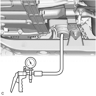
(c) Check that there is no change in the needle movement of the vacuum pump gauge.
OK:
Vacuum pressure holds.
(d) Check that there is no fluid leakage caused by a break in the diaphragm.
(e) Connect the vacuum hose to the front engine mounting insulator.
6. INSTALL REAR ENGINE UNDER COVER LH
Click here
7. INSTALL NO. 1 ENGINE UNDER COVER
Click here
8. INSTALL FRONT WHEEL OPENING EXTENSION PAD LH
Click here
9. INSTALL FRONT WHEEL OPENING EXTENSION PAD RH
Click here
READ NEXT:
 Removal
REMOVAL PROCEDURE 1. REMOVE VACUUM SWITCHING VALVE (for Active Control Engine Mount System)
Click here 2. REMOVE V-BANK COVER SUB-ASSEMBLY
Click here
3. REMOVE FRONT WHEEL OPENING EX
Installation
INSTALLATION PROCEDURE 1. INSTALL FRONT ENGINE MOUNTING INSULATOR
(a) Install the stay to the front engine mounting insulator with the nut.
Torque: 6.0 N·m {61 kgf·cm, 53 in·lbf} (b) Install t
SEE MORE:
Rear Speed Sensor
ComponentsCOMPONENTS ILLUSTRATION
*A w/o Electric Parking Brake System
- -
*1 PARKING BRAKE SHOE ADJUSTING HOLE PLUG
*2 REAR AXLE HUB AND BEARING ASSEMBLY
*3 REAR DISC
*4 REAR DISC BRAKE CALIPER ASSEMBLY
*5 SKID CONTROL SENSOR WIRE
Terminals Of Ecm
TERMINALS OF ECM ECM
HINT: The standard voltage and resistance of each ECM terminal is shown in the table below.
In the table, first follow the information under "Condition". Look under "Terminal No. (Symbol)" for the terminals to be inspected. The standard voltage or resistance between the ter
