Toyota Camry (XV70): Removal
REMOVAL
PROCEDURE
1. REMOVE VACUUM SWITCHING VALVE (for Active Control Engine Mount System)
Click here .gif)
2. REMOVE V-BANK COVER SUB-ASSEMBLY
Click here
3. REMOVE FRONT WHEEL OPENING EXTENSION PAD LH
Click here
4. REMOVE FRONT WHEEL OPENING EXTENSION PAD RH
Click here
5. REMOVE NO. 1 ENGINE UNDER COVER
Click here
6. REMOVE REAR ENGINE UNDER COVER LH
Click here
7. REMOVE FRONT ENGINE MOUNTING INSULATOR
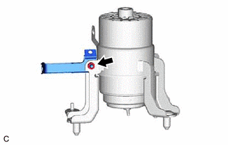
| (a) Disengage the 2 clamps to separate the vacuum hoses from the front engine mounting insulator. |
|
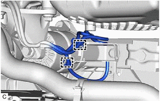
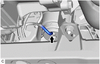
| (b) Disconnect the vacuum hose from the front engine mounting insulator. |
|
(c) Support the engine assembly with transaxle using a jack and wooden block.
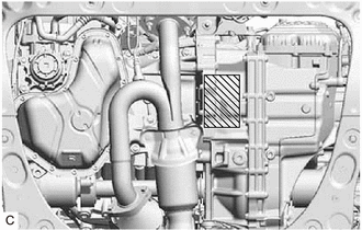
.png) |
Wooden Block Placement Location |
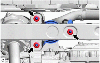
| (d) Remove the 4 bolts and front engine mounting bracket. |
|
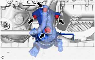
| (e) Remove the 3 nuts and front engine mounting insulator from the front frame assembly. |
|
| (f) Remove the nut and stay from the front engine mounting insulator. |
|
READ NEXT:
 Installation
INSTALLATION PROCEDURE 1. INSTALL FRONT ENGINE MOUNTING INSULATOR
(a) Install the stay to the front engine mounting insulator with the nut.
Torque: 6.0 N·m {61 kgf·cm, 53 in·lbf} (b) Install t
Components
COMPONENTS ILLUSTRATION
*1 REAR ENGINE MOUNTING INSULATOR
*2 VACUUM HOSE
*3 WIRE HARNESS CLAMP BRACKET
- -
Tightening torque for "Major areas invol
SEE MORE:
Inspection
INSPECTION PROCEDURE 1. INSPECT SLIDING ROOF SWITCH (ROOF CONSOLE BOX SUB-ASSEMBLY)
(a) Measure the resistance according to the value(s) in the table below.
Standard Resistance:
Tester Connection
Condition Specified Condition
3 - 15 UP switch pressed
Components
COMPONENTS ILLUSTRATION
*1 INSTRUMENT PANEL JUNCTION BLOCK ASSEMBLY WITH MAIN BODY ECU
*2 NO. 3 INSTRUMENT PANEL TO COWL BRACE SUB-ASSEMBLY
N*m (kgf*cm, ft.*lbf): Specified torque
- - ILLUSTRATION
*1 MAIN BODY ECU (MULTIPLEX NETWORK BODY ECU
