
Toyota Camry (XV70): Inspection
INSPECTION
PROCEDURE
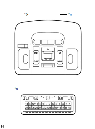
1. INSPECT SLIDING ROOF SWITCH (ROOF CONSOLE BOX SUB-ASSEMBLY)
| (a) Measure the resistance according to the value(s) in the table below. Standard Resistance:
If the result is not as specified, replace the sliding roof switch (roof console box sub-assembly). |
|
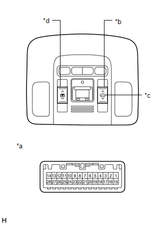
2. INSPECT PANORAMIC MOON ROOF SWITCH (ROOF CONSOLE BOX SUB-ASSEMBLY)
| (a) Measure the resistance according to the value(s) in the table below. Standard Resistance:
If the result is not as specified, replace the panoramic moon roof switch (roof console box sub-assembly). |
|
READ NEXT:
 Installation
INSTALLATION PROCEDURE 1. INSTALL ROOF CONSOLE BOX SUB-ASSEMBLY
2. INSTALL TELEPHONE MICROPHONE ASSEMBLY Click here
3. INSTALL ROOF CONSOLE BOX ASSEMBLY
Click here
Precaution
PRECAUTION PRECAUTION FOR DISCONNECTING CABLE FROM NEGATIVE BATTERY TERMINAL
NOTICE: When disconnecting the cable from the negative (-) battery terminal, initialize the following systems after the
SEE MORE:
Components
COMPONENTS ILLUSTRATION
*1 FRONT ENGINE MOUNTING INSULATOR
*2 NO. 1 ENGINE UNDER COVER
*3 REAR ENGINE UNDER COVER LH
*4 V-BANK COVER SUB-ASSEMBLY
*5 VACUUM HOSE
*6 FRONT ENGINE MOUNTING BRACKET
*7 STAY
*8 FRONT WHEEL OPENING E
Terminals Of Ecu
TERMINALS OF ECU HINT: Check from the rear of the connector while it is connected to the components.
RADIO AND DISPLAY RECEIVER ASSEMBLY
Terminal No. (Symbol) Wiring Color
Terminal Description Condition
Specified Condition
K4-1 (FR+) - K3-1 (GND1)
W - BR Soun
