Toyota Camry (XV70): Components
COMPONENTS
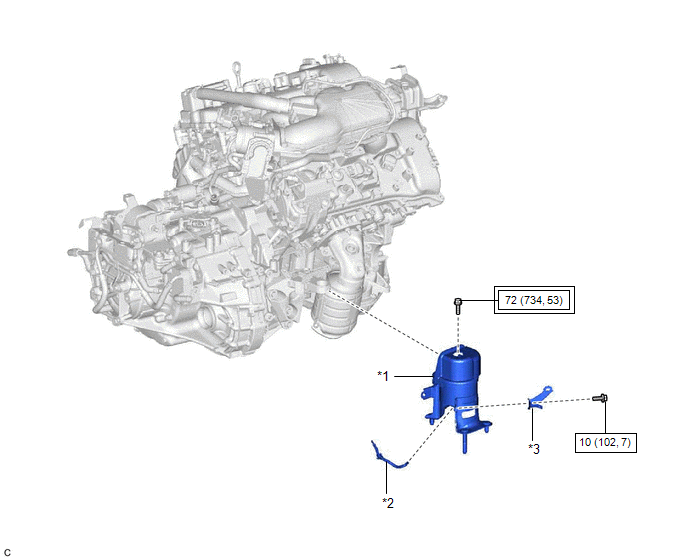
ILLUSTRATION
|
*1 | REAR ENGINE MOUNTING INSULATOR |
*2 | VACUUM HOSE |
|
*3 | WIRE HARNESS CLAMP BRACKET |
- | - |
.png) |
Tightening torque for "Major areas involving basic vehicle performance such as moving/turning/stopping": N*m (kgf*cm, ft.*lbf) |
.png) |
N*m (kgf*cm, ft.*lbf): Specified torque |
READ NEXT:
 On-vehicle Inspection
ON-VEHICLE INSPECTION CAUTION / NOTICE / HINT
HINT: Refer to Problem Symptoms Table. Click here
PROCEDURE
1. REMOVE FRONT WHEEL OPENING EXTENSION PAD LH Click here
2. REMOVE FRONT
Removal
REMOVAL CAUTION / NOTICE / HINT
The necessary procedures (adjustment, calibration, initialization, or registration) that must be performed after parts are removed and installed, or replaced during r
Installation
INSTALLATION PROCEDURE 1. INSTALL REAR ENGINE MOUNTING INSULATOR
(a) Engage the clamp and install the vacuum hose to the rear engine mounting insulator.
(b) Install the wire harness clamp bracket
SEE MORE:
Components
COMPONENTS ILLUSTRATION
*A w/o Courtesy Light
*B w/ Courtesy Light
*C for Front Passenger Side
*D for Driver Side
*1 COURTESY LIGHT ASSEMBLY
*2 FRONT ARMREST ASSEMBLY
*3 FRONT DOOR ARMREST COVER SUB-ASSEMBLY
*4 FRONT
Parts Location
PARTS LOCATION ILLUSTRATION
*1 ECM
*2 ENGINE ROOM RELAY BLOCK AND JUNCTION BLOCK ASSEMBLY
- INJ FUSE *3
IGNITION COIL ASSEMBLY
*4 SPARK PLUG
© 2023-2026 Copyright www.tocamry.com
