
Toyota Camry (XV70): Installation
INSTALLATION
PROCEDURE
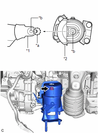
1. INSTALL REAR ENGINE MOUNTING INSULATOR
(a) Engage the clamp and install the vacuum hose to the rear engine mounting insulator.
(b) Install the wire harness clamp bracket to the rear engine mounting insulator with the bolt.
Torque:
10 N·m {102 kgf·cm, 7 ft·lbf}
| (c) Align the hole of the rear engine mounting insulator with the protrusion of the rear engine mounting bracket, slide the rear engine mounting insulator onto the rear engine mounting bracket to align the holes and install the rear engine mounting insulator with the bolt. Torque: 72 N·m {734 kgf·cm, 53 ft·lbf} |
|
2. INSTALL FRONT FRAME ASSEMBLY
Click here
.gif)
READ NEXT:
 Components
COMPONENTS ILLUSTRATION
*1 V-BANK COVER SUB-ASSEMBLY
*2 AIR FUEL RATIO SENSOR (for Bank 1)
*3 AIR FUEL RATIO SENSOR (for Bank 2)
- -
N*m (kgf*cm, f
Removal
REMOVAL CAUTION / NOTICE / HINT
The necessary procedures (adjustment, calibration, initialization or registration) that must be performed after parts are removed and installed, or replaced during ai
SEE MORE:
Right Rear Wheel Speed Sensor Circuit Short to Ground or Open (C051214)
DESCRIPTION Refer to DTC C051212 Click here
DTC No. Detection Item
DTC Detection Condition Trouble Area
C051214 Right Rear Wheel Speed Sensor Circuit Short to Ground or Open
A short or open circuit is detected in the speed sensor signal circuit for 0.12 seconds or
Evaporative Emission System Incorrect Purge Flow Actuator Stuck On (P04417E,P04417F,P04419C)
DTC SUMMARY
DTC No. Detection Item
DTC Detection Condition Trouble Area
MIL Memory
Note P04417E
Evaporative Emission System Incorrect Purge Flow Actuator Stuck On
Leak detection pump creates negative pressure (vacuum) in EVAP system and EVAP system pressure
© 2023-2026 Copyright www.tocamry.com
