Toyota Camry (XV70): Components
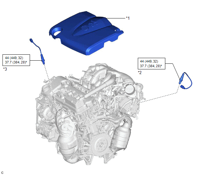
COMPONENTS
ILLUSTRATION
|
*1 | V-BANK COVER SUB-ASSEMBLY |
*2 | AIR FUEL RATIO SENSOR (for Bank 1) |
|
*3 | AIR FUEL RATIO SENSOR (for Bank 2) |
- | - |
.png) |
N*m (kgf*cm, ft.*lbf): Specified torque |
* | For use with SST |
READ NEXT:
 Removal
REMOVAL CAUTION / NOTICE / HINT
The necessary procedures (adjustment, calibration, initialization or registration) that must be performed after parts are removed and installed, or replaced during ai
Inspection
INSPECTION PROCEDURE 1. INSPECT AIR FUEL RATIO SENSOR (for Bank 1)
(a) Measure the resistance according to the value(s) in the table below.
Standard Resistance:
Tester Connection Co
Installation
INSTALLATION PROCEDURE 1. INSTALL AIR FUEL RATIO SENSOR (for Bank 1)
HINT: Perform "Inspection After Repair" after replacing the air fuel ratio sensor.
Click here
(a) Using SST, instal
SEE MORE:
Inspection
INSPECTION PROCEDURE 1. INSPECT FUEL INJECTOR ASSEMBLY
(a) Check the resistance.
(1) Measure the resistance according to the value(s) in the table below.
Standard Resistance:
Tester Connection Condition
Specified Condition 1 - 2
20°C (68°F) 11.6 to 12.4 ]
Blind Spot Monitor Sensor Communication Stop Mode
DESCRIPTION
Detection Item Symptom
Trouble Area Blind Spot Monitor Sensor Communication Stop Mode
Any of the following conditions are met:
Communication stop for "Blind Spot Monitor Master" is indicated on the "Communication Bus Check" screen of the Techstream.
Cl
© 2023-2026 Copyright www.tocamry.com
