Toyota Camry (XV70): Installation
INSTALLATION
PROCEDURE
1. INSTALL AIR FUEL RATIO SENSOR (for Bank 1)
HINT:
Perform "Inspection After Repair" after replacing the air fuel ratio sensor.
Click here .gif)
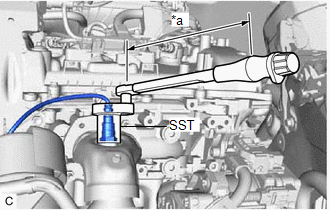
| (a) Using SST, install the air fuel ratio sensor to the exhaust manifold assembly RH (TWC: Front Catalyst). SST: 09224-00012 Torque: Specified tightening torque : 44 N·m {449 kgf·cm, 32 ft·lbf} NOTICE: If the air fuel ratio sensor has been struck or dropped, replace it. HINT:
|
|
(b) Engage the 2 wire harness clamps.
(c) Connect the air fuel ratio sensor connector.
2. INSTALL AIR FUEL RATIO SENSOR (for Bank 2)
HINT:
Perform "Inspection After Repair" after replacing the air fuel ratio sensor.
Click here
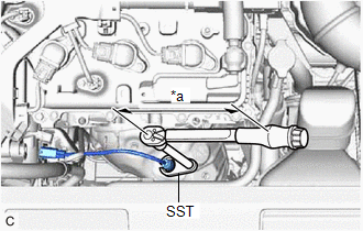
| (a) Using SST, install the air fuel ratio sensor to the exhaust manifold assembly LH (TWC: Front Catalyst). SST: 09224-00012 Torque: Specified tightening torque : 44 N·m {449 kgf·cm, 32 ft·lbf} NOTICE: If the air fuel ratio sensor has been struck or dropped, replace it. HINT:
|
|
(b) Connect the air fuel ratio sensor connector.
(c) Engage the wire harness clamp.
3. INSTALL V-BANK COVER SUB-ASSEMBLY
Click here
4. INSPECT FOR EXHAUST GAS LEAK
Click here
5. PERFORM INITIALIZATION
(a) Perform "Inspection After Repair" after replacing an air fuel ratio sensor.
Click here
READ NEXT:
 Components
COMPONENTS ILLUSTRATION
*1 FRONT FENDER APRON SEAL RH
*2 V-BANK COVER SUB-ASSEMBLY
N*m (kgf*cm, ft.*lbf): Specified torque
- - ILLUSTRATION
*1
On-vehicle Inspection
ON-VEHICLE INSPECTION PROCEDURE
1. INSPECT CAMSHAFT TIMING OIL CONTROL SOLENOID ASSEMBLY (a) Connect the Techstream to the DLC3.
(b) Start the engine. (c) Turn the Techstream on. (d) Inspect the c
SEE MORE:
FL Speed Sensor Wrong Installation (X0451)
DESCRIPTION
Code Tester Display
Measurement Item Trouble Area
X0451 FL Speed Sensor Wrong Installation
History of front speed sensor LH being installed incorrectly
Front speed sensor LH PROCEDURE
1.
CHECK FOR DTCs (HEALTH CHECK) (a) Perform the H
Main Body ECU Communication Stop Mode
DESCRIPTION
Detection Item Symptom
Trouble Area Main Body ECU Communication Stop Mode
Any of the following conditions are met:
Communication stop for "Main Body" is indicated on the "Communication Bus Check" screen of the Techstream.
Click here
