Toyota Camry (XV70): Components
COMPONENTS
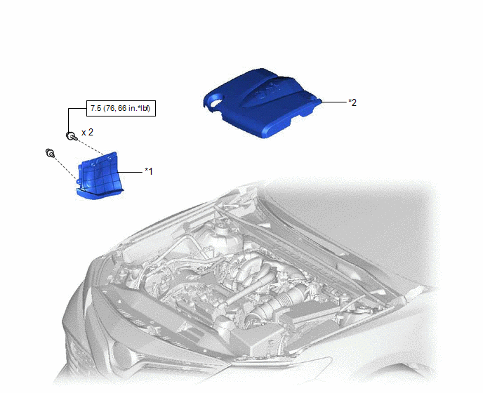
ILLUSTRATION
|
*1 | FRONT FENDER APRON SEAL RH |
*2 | V-BANK COVER SUB-ASSEMBLY |
.png) |
N*m (kgf*cm, ft.*lbf): Specified torque |
- | - |
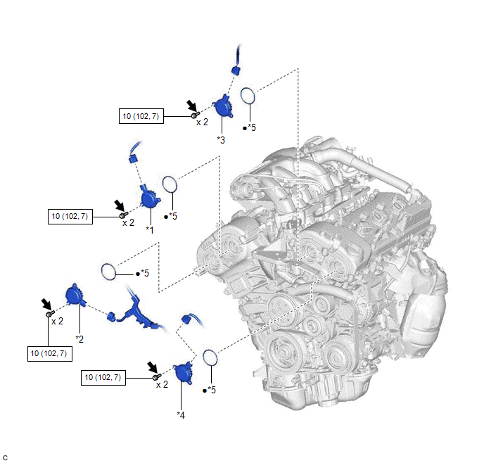
ILLUSTRATION
|
*1 | CAMSHAFT TIMING OIL CONTROL SOLENOID ASSEMBLY (for Intake Side of Bank 1) |
*2 | CAMSHAFT TIMING OIL CONTROL SOLENOID ASSEMBLY (for Exhaust Side of Bank 1) |
|
*3 | CAMSHAFT TIMING OIL CONTROL SOLENOID ASSEMBLY (for Intake Side of Bank 2) |
*4 | CAMSHAFT TIMING OIL CONTROL SOLENOID ASSEMBLY (for Exhaust Side of Bank 2) |
|
*5 | O-RING |
- | - |
|
|
N*m (kgf*cm, ft.*lbf): Specified torque |
● | Non-reusable part |
.png) |
Adhesive 1324 | ★ |
Precoated part |
READ NEXT:
 On-vehicle Inspection
ON-VEHICLE INSPECTION PROCEDURE
1. INSPECT CAMSHAFT TIMING OIL CONTROL SOLENOID ASSEMBLY (a) Connect the Techstream to the DLC3.
(b) Start the engine. (c) Turn the Techstream on. (d) Inspect the c
Removal
REMOVAL PROCEDURE 1. REMOVE V-BANK COVER SUB-ASSEMBLY
Click here
2. REMOVE CAMSHAFT TIMING OIL CONTROL SOLENOID ASSEMBLY (for Exhaust Side of Bank 2)
(a) Disconnect the camshaft ti
Inspection
INSPECTION PROCEDURE 1. INSPECT CAMSHAFT TIMING OIL CONTROL SOLENOID ASSEMBLY
HINT: Use the same procedure for the intake side and exhaust side.
(a) Check the resistance.
(1) Measure the res
SEE MORE:
Fuel Rail Pressure Sensor "A" Circuit Short to Ground (P019011)
DESCRIPTION
The fuel pressure sensor (for high pressure side) is installed on the fuel delivery pipe (for high pressure side). The fuel pressure sensor (for high pressure side) changes the fuel pressure for high pressure side into an electrical signal and sends the signal to the ECM. Then the ECM
Removal
REMOVAL CAUTION / NOTICE / HINT
The necessary procedures (adjustment, calibration, initialization or registration) that must be performed after parts are removed and installed, or replaced during fuel injector assembly removal/installation are shown below. Necessary Procedures After Parts Removed/
© 2023-2026 Copyright www.tocamry.com
