Toyota Camry (XV70): Inspection
INSPECTION
PROCEDURE
1. INSPECT CAMSHAFT TIMING OIL CONTROL SOLENOID ASSEMBLY
HINT:
Use the same procedure for the intake side and exhaust side.
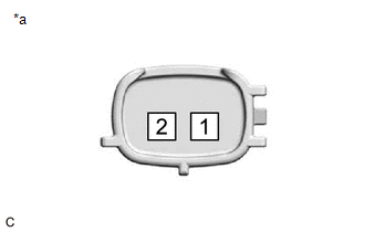
(a) Check the resistance.
| (1) Measure the resistance according to the value(s) in the table below. Standard Resistance:
If the result is not as specified, replace the camshaft timing oil control solenoid assembly. |
|
(b) Stroke Amount Inspection
| (1) Using vernier calipers, measure length (A) and (B) with the shaft of the camshaft timing oil control solenoid assembly set in the respective positions shown in the illustration. NOTICE: Do not apply battery voltage to the terminals of the camshaft timing oil control solenoid assembly. HINT: If the shaft does not extend under its own weight, extend the shaft with your fingers. |
|
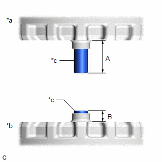
(2) Calculate the stroke amount based on the difference of length (A) and (B).
Standard:
6.5 mm (0.256 in.) or more
HINT:
Stroke amount = length (A) - length (B)
If the value is not as specified, replace the camshaft timing oil control solenoid assembly.
READ NEXT:
 Installation
INSTALLATION PROCEDURE 1. INSTALL CAMSHAFT TIMING OIL CONTROL SOLENOID ASSEMBLY (for Intake Side of Bank 2)
(a) Apply engine oil to a new O-ring and install it to the camshaft timing oil control
Components
COMPONENTS ILLUSTRATION
*1 FRONT FENDER APRON SEAL RH
*2 V-BANK COVER SUB-ASSEMBLY
N*m (kgf*cm, ft.*lbf): Specified torque
- - ILLUSTRATION
*1
SEE MORE:
Left Front Wheel Speed Sensor Supply Voltage Circuit Short to Ground or Open (C14E014)
DESCRIPTION Refer to DTC C050012 Click here
DTC No. Detection Item
DTC Detection Condition Trouble Area
C14E014 Left Front Wheel Speed Sensor Supply Voltage Circuit Short to Ground or Open
An open or short in the speed sensor power supply circuit is detected for 0.
Calibration
CALIBRATION
NOTICE:
Initial AWD functions such as acceleration are sometimes affected unless backup memory is cleared.
When the yaw rate and acceleration sensor (airbag sensor assembly) is replaced, Reset Memory must be performed.
RESET MEMORY (a) Turn the ignition switch off. (b) Co
