Toyota Camry (XV70): Installation
INSTALLATION
PROCEDURE
1. INSTALL CAMSHAFT TIMING OIL CONTROL SOLENOID ASSEMBLY (for Intake Side of Bank 2)
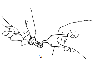
| (a) Apply engine oil to a new O-ring and install it to the camshaft timing oil control solenoid assembly as shown in the illustration. NOTICE: Do not damage the O-ring. |
|

| (b) Apply adhesive to 2 or 3 threads of 2 new bolts. Adhesive: Toyota Genuine Adhesive 1324, Three Bond 1324 or equivalent |
|
(c) Install the camshaft timing oil control solenoid assembly to the timing chain cover assembly with the 2 bolts.
Torque:
10 N·m {102 kgf·cm, 7 ft·lbf}
NOTICE:
- If the camshaft timing oil control solenoid assembly has been struck or dropped, replace it.
- Make sure that the O-ring is not cracked or moved out of place when installing the camshaft timing oil control solenoid assembly.
(d) Connect the camshaft timing oil control solenoid assembly connector.
2. INSTALL ENGINE ASSEMBLY WITH TRANSAXLE
Click here
.gif)
3. INSTALL CAMSHAFT TIMING OIL CONTROL SOLENOID ASSEMBLY (for Exhaust Side of Bank 1)
| (a) Apply engine oil to a new O-ring and install it to the camshaft timing oil control solenoid assembly as shown in the illustration. NOTICE: Do not damage the O-ring. |
|
| (b) Apply adhesive to 2 or 3 threads of 2 new bolts. Adhesive: Toyota Genuine Adhesive 1324, Three Bond 1324 or equivalent |
|
(c) Install the camshaft timing oil control solenoid assembly to the timing chain cover assembly with the 2 bolts.
Torque:
10 N·m {102 kgf·cm, 7 ft·lbf}
NOTICE:
- If the camshaft timing oil control solenoid assembly has been struck or dropped, replace it.
- Make sure that the O-ring is not cracked or moved out of place when installing the camshaft timing oil control solenoid assembly.
(d) Connect the camshaft timing oil control solenoid assembly connector.
4. INSTALL FRONT FENDER APRON SEAL RH
Click here
5. INSTALL CAMSHAFT TIMING OIL CONTROL SOLENOID ASSEMBLY (for Intake Side of Bank 1)
| (a) Apply engine oil to a new O-ring and install it to the camshaft timing oil control solenoid assembly as shown in the illustration. NOTICE: Do not damage the O-ring. |
|
| (b) Apply adhesive to 2 or 3 threads of 2 new bolts. Adhesive: Toyota Genuine Adhesive 1324, Three Bond 1324 or equivalent |
|
(c) Install the camshaft timing oil control solenoid assembly to the timing chain cover assembly with the 2 bolts.
Torque:
10 N·m {102 kgf·cm, 7 ft·lbf}
NOTICE:
- If the camshaft timing oil control solenoid assembly has been struck or dropped, replace it.
- Make sure that the O-ring is not cracked or moved out of place when installing the camshaft timing oil control solenoid assembly.
(d) Engage the clamp to connect the engine wire.
(e) Connect the camshaft timing oil control solenoid assembly connector.
6. INSTALL CAMSHAFT TIMING OIL CONTROL SOLENOID ASSEMBLY (for Exhaust Side of Bank 2)
| (a) Apply engine oil to a new O-ring and install it to the camshaft timing oil control solenoid assembly as shown in the illustration. NOTICE: Do not damage the O-ring. |
|
| (b) Apply adhesive to 2 or 3 threads of 2 new bolts. Adhesive: Toyota Genuine Adhesive 1324, Three Bond 1324 or equivalent |
|
(c) Install the camshaft timing oil control solenoid assembly to the timing chain cover assembly with the 2 bolts.
Torque:
10 N·m {102 kgf·cm, 7 ft·lbf}
NOTICE:
- If the camshaft timing oil control solenoid assembly has been struck or dropped, replace it.
- Make sure that the O-ring is not cracked or moved out of place when installing the camshaft timing oil control solenoid assembly.
(d) Connect the camshaft timing oil control solenoid assembly connector.
7. INSPECT FOR ENGINE OIL LEAK
Click here
8. INSTALL V-BANK COVER SUB-ASSEMBLY
Click here
READ NEXT:
 Components
COMPONENTS ILLUSTRATION
*1 FRONT FENDER APRON SEAL RH
*2 V-BANK COVER SUB-ASSEMBLY
N*m (kgf*cm, ft.*lbf): Specified torque
- - ILLUSTRATION
*1
Removal
REMOVAL PROCEDURE 1. REMOVE FRONT WHEEL RH
Click here 2. REMOVE FRONT FENDER APRON SEAL RH
Click here
3. REMOVE V-BANK COVER SUB-ASSEMBLY Click here
4. REMOVE CAMSHAFT TI
SEE MORE:
Multi-axis Acceleration Sensor Module "A" Signal Stuck In Range (C05202A)
DESCRIPTION The airbag sensor assembly has a built-in yaw rate and acceleration sensor and detects the vehicle condition.
The skid control ECU (brake actuator assembly) memorizes the range of the acceleration sensor (airbag sensor assembly) and the range of vehicle speed calculated using each spee
Short to GND in Outer Mirror Indicator(Slave) (C1AB3)
DESCRIPTION This DTC is stored when the blind spot monitor sensor LH detects a short to ground in the outer rear view mirror indicator LH.
DTC No. Detection Item
DTC Detection Condition Trouble Area
C1AB3 Short to GND in Outer Mirror Indicator(Slave) Both of the following
