Toyota Camry (XV70): Components
COMPONENTS
ILLUSTRATION
.png)
|
*1 | FRONT FENDER APRON SEAL RH |
*2 | V-BANK COVER SUB-ASSEMBLY |
.png) |
N*m (kgf*cm, ft.*lbf): Specified torque |
- | - |
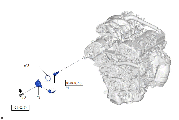
ILLUSTRATION
|
*1 | CAMSHAFT TIMING GEAR BOLT |
*2 | O-RING |
|
*3 | CAMSHAFT TIMING OIL CONTROL SOLENOID ASSEMBLY (for Exhaust Side of Bank 1) |
- | - |
|
|
N*m (kgf*cm, ft.*lbf): Specified torque |
● | Non-reusable part |
.png) |
Adhesive 1324 | ★ |
Precoated part |
READ NEXT:
 Removal
REMOVAL PROCEDURE 1. REMOVE FRONT WHEEL RH
Click here 2. REMOVE FRONT FENDER APRON SEAL RH
Click here
3. REMOVE V-BANK COVER SUB-ASSEMBLY Click here
4. REMOVE CAMSHAFT TI
Inspection
INSPECTION PROCEDURE 1. INSPECT CAMSHAFT TIMING GEAR BOLT
(a) Check the stroke of the plunger in the center of the camshaft timing gear bolt.
Standard Stroke: 2.2 mm (0.0866 in.) or more HIN
Installation
INSTALLATION PROCEDURE 1. INSTALL CAMSHAFT TIMING GEAR BOLT
(a) Make sure that the No. 1 cylinder is at TDC/compression. HINT:
Check that the cutout of the camshaft timing gear assembly is at the
SEE MORE:
Removal
REMOVAL CAUTION / NOTICE / HINT
The necessary procedures (adjustment, calibration, initialization or registration) that must be performed after parts are removed and installed, or replaced during rear door belt moulding removal/installation are shown below. Necessary Procedure After Parts Removed
Components
COMPONENTS ILLUSTRATION
*1 AIR CLEANER CAP WITH AIR CLEANER HOSE
*2 ENGINE COOLANT TEMPERATURE SENSOR
*3 VACUUM HOSE
*4 NO. 1 FUEL VAPOR FEED HOSE
*5 NO. 2 VENTILATION HOSE
- -
© 2023-2026 Copyright www.tocamry.com
