Toyota Camry (XV70): On-vehicle Inspection
ON-VEHICLE INSPECTION
PROCEDURE
1. OPERATION CHECK
(a) Slide the clip and disconnect the union to check valve hose from the vacuum pump assembly.
| (b) Connect the hose of the vacuum gauge to the vacuum pump assembly. |
|
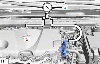
(c) Start the engine and warm it up for more than 2 minutes.
(d) With the engine idling, check the vacuum of the vacuum pump assembly.
Standard Pressure:
More than 86.7 kPa (650 mmHg, 25.6 in.Hg)
If the pressure is less than the standard, disassemble and inspect the vacuum pump. If necessary, replace the vacuum pump assembly.
Click here .gif)
HINT:
Always perform this operation check procedure after replacing or servicing the vacuum pump assembly.
(e) Remove the vacuum gauge from the vacuum pump assembly.
(f) Connect the union to check valve hose to the vacuum pump assembly, and slide the clip to secure it.
READ NEXT:
 Removal
REMOVAL CAUTION / NOTICE / HINT
NOTICE: This procedure includes the removal of small-head bolts. Refer to Small-Head Bolts of Basic Repair Hint to identify the small-head bolts.
Click here
Disassembly
DISASSEMBLY PROCEDURE 1. REMOVE END COVER
(a) To prevent the coupling of the vacuum pump assembly from contacting the workbench, support the vacuum pump assembly with wooden blocks or an equival
Reassembly
REASSEMBLY PROCEDURE 1. CLEAN VACUUM PUMP HOUSING
(a) Clean the inside surface of the vacuum pump housing. 2. INSTALL VACUUM PUMP ROTOR
(a) Clean the vacuum pump rotor. (b) Apply engine oil to the
SEE MORE:
Operation Check
OPERATION CHECK STORAGE CHECK
NOTICE:
When replacing the radio and display receiver assembly, always replace it with a new one. If a radio and display receiver assembly which was installed to another vehicle is used, the following may occur:
A communication malfunction DTC may be stored.
Removal
REMOVAL PROCEDURE 1. REMOVE V-BANK COVER SUB-ASSEMBLY
Click here
2. REMOVE NO. 1 VACUUM SWITCHING VALVE ASSEMBLY (for ACIS)
(a) Disconnect the No. 1 vacuum switching valve assembly (for ACIS) connector.
(b) Disconnect the 2 vacuum hose assemblies from the No.
