Toyota Camry (XV70): Installation
Toyota Camry Repair Manual XV70 (2018-2024) / Brake / Brake System (other) / Vacuum Warning Switch / Installation
INSTALLATION
PROCEDURE
1. INSTALL CHECK VALVE GROMMET
(a) Install a new check valve grommet to the brake booster assembly.
2. INSTALL VACUUM WARNING SWITCH ASSEMBLY
(a) Install the vacuum warning switch assembly to the brake booster assembly as shown in the illustration.
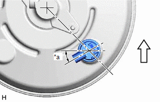
|
*a | 30 |
READ NEXT:
 Components
COMPONENTS ILLUSTRATION
*1 NO. 2 PARKING BRAKE WIRE ASSEMBLY
*2 PARKING BRAKE ACTUATOR ASSEMBLY
*3 O-RING
- -
Tightening torque for "Major areas in
SEE MORE:
Transmitter ID not Registered (Main) (C2171)
DESCRIPTION The IDs of each tire pressure warning valve and transmitter are registered to the tire pressure warning ECU and receiver.
When the ECU detects that a transmitter ID code is not registered in the ECU, this DTC is stored.
DTC No. Detection Item
DTC Detection Condition Trou
Throttle/Pedal Position Sensor/Switch "B" Circuit Short to Ground (P022011)
DESCRIPTION Refer to DTC P012011. Click here
DTC No. Detection Item
DTC Detection Condition Trouble Area
MIL Memory
Note P022011
Throttle/Pedal Position Sensor/Switch "B" Circuit Short to Ground
The output voltage of VTA2 is less than 2.05 V for 2 secon
© 2023-2026 Copyright www.tocamry.com
