
Toyota Camry (XV70): Removal
REMOVAL
CAUTION / NOTICE / HINT
The necessary procedures (adjustment, calibration, initialization, or registration) that must be performed after parts are removed and installed, or replaced during rear door lock with motor assembly removal/installation are shown below.
Necessary Procedure After Parts Removed/Installed/Replaced|
Replaced Part or Performed Procedure |
Necessary Procedure | Effect/Inoperative Function when Necessary Procedure not Performed |
Link |
|---|---|---|---|
|
Disconnect cable from negative battery terminal |
Perform steering sensor zero point calibration |
Lane Tracing Assist System |
|
|
Pre-collision system | |||
|
Memorize steering angle neutral point |
Parking assist monitor system |
| |
|
Panoramic view monitor system |
| ||
| Initialize power window control system |
|
|
HINT:
- Use the same procedure for the RH side and LH side.
- The following procedure is for the LH side.
PROCEDURE
1. PRECAUTION
NOTICE:
After turning the ignition switch off, waiting time may be required before disconnecting the cable from the negative (-) battery terminal. Therefore, make sure to read the disconnecting the cable from the negative (-) battery terminal notices before proceeding with work.
Click here .gif)
2. DISCONNECT CABLE FROM NEGATIVE BATTERY TERMINAL
for A25A-FKS:
Click here
for 2GR-FKS:
Click here
3. REMOVE REAR DOOR ARMREST COVER SUB-ASSEMBLY
Click here
4. REMOVE REAR POWER WINDOW REGULATOR SWITCH ASSEMBLY WITH REAR DOOR UPPER ARMREST BASE PANEL
Click here
5. REMOVE REAR ARMREST ASSEMBLY
Click here
6. REMOVE REAR DOOR TRIM BOARD SUB-ASSEMBLY
Click here
7. REMOVE REAR DOOR INNER GLASS WEATHERSTRIP
Click here
8. REMOVE REAR DOOR NO. 2 SERVICE HOLE COVER
Click here
9. REMOVE REAR DOOR SERVICE HOLE COVER
Click here
10. REMOVE REAR DOOR NO. 1 VENT SEAL
Click here
11. REMOVE REAR DOOR PANEL PROTECTOR
Click here
12. REMOVE REAR DOOR GLASS RUN
Click here
13. DISCONNECT REAR DOOR WEATHERSTRIP
(a) Disconnect the rear door weatherstrip until the screw of the rear door rear lower window frame sub-assembly is visible.
14. REMOVE REAR DOOR REAR LOWER WINDOW FRAME SUB-ASSEMBLY
Click here
15. REMOVE REAR DOOR QUARTER WINDOW GLASS
Click here
16. REMOVE REAR DOOR GLASS SUB-ASSEMBLY
Click here
17. REMOVE REAR DOOR LOCK WITH MOTOR ASSEMBLY
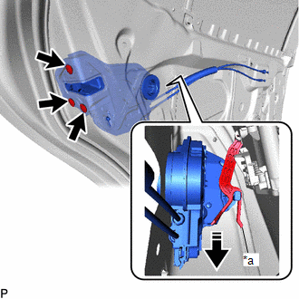
(a) Using a T30 "TORX" socket wrench, remove the 3 screws.
|
*a | Release Plate |
.png) |
Remove in this Direction |
(b) Move the rear door lock with motor assembly downward to disconnect it from the release plate of the rear door outside handle frame sub-assembly, and remove the rear door lock with motor assembly.
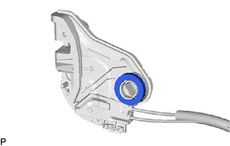
(c) When reusing the rear door lock with motor assembly:
| (1) Remove the door lock wiring harness seal from the rear door lock with motor assembly. |
|
18. REMOVE REAR DOOR LOCK COVER SUB-ASSEMBLY
| (a) Using a screwdriver, disengage the 2 claws as shown in the illustration. |
|
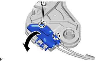
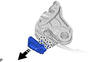
(b) Disengage the 2 claws to remove the rear door lock cover sub-assembly as shown in the illustration.
|
|
Remove in this Direction |
19. REMOVE REAR DOOR LOCK REMOTE CONTROL CABLE ASSEMBLY
(a) Remove the rear door lock remote control cable assembly as shown in the illustration.
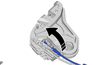
|
|
Remove in this Direction |
20. REMOVE REAR DOOR INSIDE LOCKING CABLE ASSEMBLY
(a) Remove the rear door inside locking cable assembly as shown in the illustration.
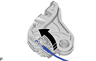
|
|
Remove in this Direction |
READ NEXT:
 Inspection
INSPECTION PROCEDURE 1. INSPECT REAR DOOR LOCK WITH MOTOR ASSEMBLY LH
(a) Check the operation of the door lock motor. (1) Apply battery voltage and check the operation of the door lock motor.
O
Installation
INSTALLATION CAUTION / NOTICE / HINT
HINT:
Use the same procedure for the RH side and LH side.
The following procedure is for the LH side.
PROCEDURE 1. INSTALL REAR DOOR INSIDE LOCKING CABLE AS
Transmitter Battery(w/ Smart Key System)
ReplacementREPLACEMENT PROCEDURE
1. REMOVE TRANSMITTER BATTERY Click here
2. INSTALL TRANSMITTER BATTERY
Click here
SEE MORE:
Definition Of Terms
DEFINITION OF TERMS
Term Definition
Monitor Description Description of what the ECM monitors and how it detects malfunctions (monitoring purpose and details).
Related DTCs Group of diagnostic trouble codes that are output by the ECM based on the same malfunction detection
Lost Communication with Sliding Sunshade ECU (B2329)
DESCRIPTION This DTC is stored when LIN communication between the roof sunshade ECU (sliding roof drive gear assembly) and main body ECU (multiplex network body ECU) stops for 10 seconds or more.
DTC No. Detection Item
DTC Detection Condition Trouble Area
B2329 Lost Communic
