Toyota Camry (XV70): Lost Communication with Sliding Sunshade ECU (B2329)
DESCRIPTION
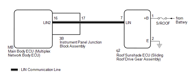
This DTC is stored when LIN communication between the roof sunshade ECU (sliding roof drive gear assembly) and main body ECU (multiplex network body ECU) stops for 10 seconds or more.
|
DTC No. | Detection Item |
DTC Detection Condition | Trouble Area |
|---|---|---|---|
|
B2329 | Lost Communication with Sliding Sunshade ECU |
No communication between roof sunshade ECU (sliding roof drive gear assembly) and main body ECU (multiplex network body ECU) for 10 seconds or more. |
|
WIRING DIAGRAM
CAUTION / NOTICE / HINT
NOTICE:
- Inspect the fuses for circuits related to this system before performing the following procedure.
- Before replacing the main body ECU (multiplex network body ECU), refer to Registration.*
Click here
.gif)
- When the roof sunshade ECU (sliding roof drive gear assembly) is replaced or removed and reinstalled, it is necessary to perform initialization.
Click here
- *: w/ Smart Key System
PROCEDURE
|
1. | INSPECT INSTRUMENT PANEL JUNCTION BLOCK ASSEMBLY |
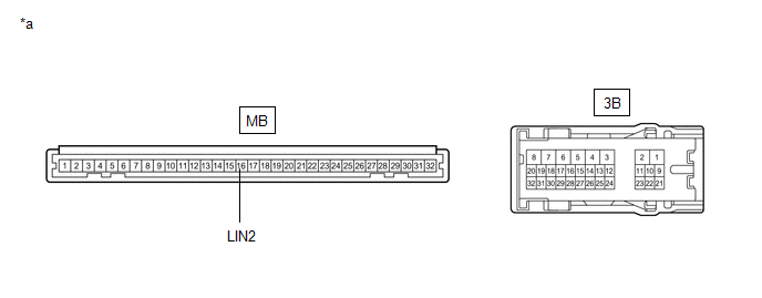
(a) Remove the instrument panel junction block assembly.
Click here
|
*a | Component without harness connected (Instrument Panel Junction Block Assembly) |
- | - |
(b) Remove the main body ECU (multiplex network body ECU) from the instrument panel junction block assembly.
(c) Measure the resistance according to the value(s) in the table below.
HINT:
This inspection is to check the LIN communication line in the instrument panel junction block assembly that connects the wire harness to the built-in main body ECU (multiplex network body ECU).
Standard Resistance:
|
Tester Connection | Condition |
Specified Condition |
|---|---|---|
|
3B-17 - MB-16 (LIN2) |
Always | Below 1 Ω |
| NG | .gif) | REPLACE INSTRUMENT PANEL JUNCTION BLOCK ASSEMBLY
|
|
.gif)
| 2. |
CHECK HARNESS AND CONNECTOR (INSTRUMENT PANEL JUNCTION BLOCK ASSEMBLY - ROOF SUNSHADE ECU (SLIDING ROOF DRIVE GEAR ASSEMBLY)) |
(a) Disconnect the q2 roof sunshade ECU (sliding roof drive gear assembly) connector.
(b) Measure the resistance according to the value(s) in the table below.
NOTICE:
Make sure that each ECU is in sleep mode before performing the inspection. To enter sleep mode, turn the ignition switch from ON to off and wait for 180 seconds or more without operating any switches.
Standard Resistance:
|
Tester Connection | Condition |
Specified Condition |
|---|---|---|
|
3B-17 -q2-7 (LIN) | Ignition switch off |
Below 1 Ω |
|
q2-7 (LIN) or 3B-17 - Body ground |
Ignition switch off | 10 kΩ or higher |
| NG | | REPAIR OR REPLACE HARNESS OR CONNECTOR |
|
| 3. |
CHECK HARNESS AND CONNECTOR (ROOF SUNSHADE ECU (SLIDING ROOF DRIVE GEAR ASSEMBLY) - BATTERY, BODY GROUND) |
(a) Measure the voltage according to the value(s) in the table below.
Standard Voltage:
|
Tester Connection | Condition |
Specified Condition |
|---|---|---|
|
q2-1 (+B) - q2-2 (E) |
Always | 11 to 14 V |
(b) Measure the resistance according to the value(s) in the table below.
Standard Resistance:
|
Tester Connection | Condition |
Specified Condition |
|---|---|---|
|
q2-2 (E) - Body ground |
Always | Below 1 Ω |
| NG | | REPAIR OR REPLACE HARNESS OR CONNECTOR |
|
| 4. |
REPLACE ROOF SUNSHADE ECU (SLIDING ROOF DRIVE GEAR ASSEMBLY) |
(a) Replace the roof sunshade ECU (sliding roof drive gear assembly).
Click here
|
| 5. |
CHECK FOR DTC |
(a) Clear the DTCs.
Click here
(b) Recheck for DTCs.
Body Electrical > Main Body > Trouble CodesOK:
DTC B2329 is not output.
| OK | | END (ROOF SUNSHADE ECU (SLIDING ROOF DRIVE GEAR ASSEMBLY) WAS DEFECTIVE) |
| NG | | REPLACE MAIN BODY ECU (MULTIPLEX NETWORK BODY ECU)
|
READ NEXT:
 Communication Malfunction between ECUs Connected by LIN (B2785)
DESCRIPTION If the certification ECU (smart key ECU assembly) detects a communication error with an ECU connected to the certification bus lines for 7 seconds or more, DTC B2785 will be stored.
No Response from ID BOX (B2789)
DESCRIPTION This DTC is stored when LIN communication between the certification ECU (smart key ECU assembly) and ID code box (immobiliser code ECU) stops for 10 seconds or more.
DTC No. Detect
Lost Communication with Power Source Control (B278C)
DESCRIPTION This DTC is stored when LIN communication between the certification ECU (smart key ECU assembly) and power management control ECU stops for 10 seconds or more.
DTC No. Detection It
SEE MORE:
AHB (Automatic High
Beam)
The Automatic High Beam uses a front camera located behind
the upper portion of the windshield to assess the brightness of
the lights of vehicles ahead, streetlights, etc., and automatically
turns the high beams on or off as necessary.
WARNING
■Limitations of the Automatic High Beam
Do not o
Components
COMPONENTS ILLUSTRATION
*A w/o Manual (SOS) Switch
*B w/ Manual (SOS) Switch
*1 INSTRUMENT PANEL SAFETY PAD SUB-ASSEMBLY
*2 NAVIGATION ANTENNA ASSEMBLY
*3 NAVIGATION ANTENNA ASSEMBLY WITH BRACKET
*4 NAVIGATION ANTENNA BRACKET
*5 NO. 3
