
Toyota Camry (XV70): Inspection
INSPECTION
PROCEDURE
1. INSPECT REAR DOOR LOCK WITH MOTOR ASSEMBLY LH
| (a) Check the operation of the door lock motor. (1) Apply battery voltage and check the operation of the door lock motor. OK:
If the result is not as specified, replace the rear door lock with motor assembly LH. |
|
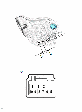
(b) Check the operation of the unlock detection switch.
(1) Measure the resistance according to the value(s) in the table below.
Standard Resistance:
|
Tester Connection | Condition |
Specified Condition |
|---|---|---|
|
6 - 9 | Locked |
10 k? or higher |
|
6 - 9 | Unlocked |
Below 1 ? |
If the result is not as specified, replace the rear door lock with motor assembly LH.
2. INSPECT REAR DOOR LOCK WITH MOTOR ASSEMBLY RH
| (a) Check the operation of the door lock motor. (1) Apply battery voltage and check the operation of the door lock motor. OK:
If the result is not as specified, replace the rear door lock with motor assembly RH. |
|
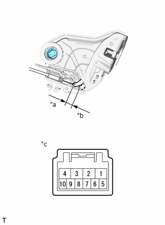
(b) Check the operation of the unlock detection switch.
(1) Measure the resistance according to the value(s) in the table below.
Standard Resistance:
|
Tester Connection | Condition |
Specified Condition |
|---|---|---|
|
6 - 9 | Locked |
10 k? or higher |
|
6 - 9 | Unlocked |
Below 1 ? |
If the result is not as specified, replace the rear door lock with motor assembly RH.
READ NEXT:
 Installation
INSTALLATION CAUTION / NOTICE / HINT
HINT:
Use the same procedure for the RH side and LH side.
The following procedure is for the LH side.
PROCEDURE 1. INSTALL REAR DOOR INSIDE LOCKING CABLE AS
Transmitter Battery(w/ Smart Key System)
ReplacementREPLACEMENT PROCEDURE
1. REMOVE TRANSMITTER BATTERY Click here
2. INSTALL TRANSMITTER BATTERY
Click here
Transmitter Battery(w/o Smart Key System)
ReplacementREPLACEMENT PROCEDURE
1. REMOVE TRANSMITTER BATTERY Click here
2. INSTALL TRANSMITTER BATTERY
Click here
SEE MORE:
Vehicle Speed Signal Circuit between Stereo Component Amplifier and Combination Meter
DESCRIPTION The stereo component amplifier assembly receives a vehicle speed signal from the combination meter assembly to control the ASL function.
HINT:
A voltage of 12 V or 5 V is output from each ECU and then input to the combination meter assembly. The signal is changed to a pulse signal
Summary of functions
The multi-information display presents the driver with a variety of driving-
related data, such as the current outside temperature. The multi-information
display can also be used to change the display settings
and other settings.
Indicators
Driving assist system status display area
Disp
