Toyota Camry (XV70): Vehicle Speed Signal Circuit between Stereo Component Amplifier and Combination Meter
DESCRIPTION
The stereo component amplifier assembly receives a vehicle speed signal from the combination meter assembly to control the ASL function.
HINT:
- A voltage of 12 V or 5 V is output from each ECU and then input to the combination meter assembly. The signal is changed to a pulse signal at the transistor in the combination meter assembly. Each ECU controls its respective systems based on this pulse signal.
- If a short occurs in any of the ECUs or in the wire harness connected to an ECU, all systems in the following diagram will not operate normally.
WIRING DIAGRAM
.png)
PROCEDURE
| 1. |
INSPECT COMBINATION METER ASSEMBLY (OUTPUT WAVEFORM) |
| (a) Check the output waveform. (1) Remove the combination meter assembly with the connector(s) still connected. (2) Connect an oscilloscope to terminal K21-6 (+S) and body ground. (3) Turn the engine switch on (IG). (4) Turn a wheel slowly. (5) Check the signal waveform according to the condition(s) in the table below.
OK: The waveform is similar to that shown in the illustration. HINT: When the system is functioning normally, one wheel revolution generates 4 pulses. As the vehicle speed increases, the width indicated by (A) in the illustration narrows. |
|
.png)
| NG | .gif) | GO TO METER / GAUGE SYSTEM
|
.gif)
|
.gif)
| 2. |
INSPECT STEREO COMPONENT AMPLIFIER ASSEMBLY (INPUT WAVEFORM) |
(a) Check the input waveform.
|
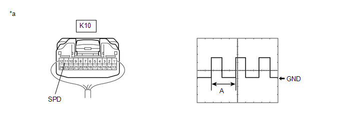
*a | Component with harness connected (Stereo Component Amplifier Assembly) |
- | - |
(1) Remove the stereo component amplifier assembly with the connector(s) still connected.
(2) Connect an oscilloscope to terminal K10-11 (SPD) and body ground.
(3) Turn the engine switch on (IG).
(4) Turn a wheel slowly.
(5) Check the signal waveform according to the condition(s) in the table below.
|
Item | Condition |
|---|---|
|
Measurement terminal |
K10-11 (SPD) - Body ground |
|
Tool setting | 5 V/DIV., 20 ms./DIV. |
|
Vehicle condition | Wheel being rotated |
OK:
The waveform is similar to that shown in the illustration.
HINT:
When the system is functioning normally, one wheel revolution generates 4 pulses. As the vehicle speed increases, the width indicated by (A) in the illustration narrows.
| OK | | PROCEED TO NEXT SUSPECTED AREA SHOWN IN PROBLEM SYMPTOMS TABLE
|
| NG | | REPAIR OR REPLACE HARNESS OR CONNECTOR |
READ NEXT:
 Reverse Signal Circuit
DESCRIPTION The radio and display receiver assembly receives a reverse signal from the BKUP LP relay. WIRING DIAGRAM
PROCEDURE
1.
CHECK BACK-UP LIGHT (a) Move the shift lever to R and
Reverse Signal Circuit between Radio Receiver Assembly and Navigation ECU
DESCRIPTION This circuit includes the navigation ECU and radio and display receiver assembly. WIRING DIAGRAM
PROCEDURE
1.
CHECK HARNESS AND CONNECTOR (RADIO AND DISPLAY RECEIVER ASSEMBLY
Start Up Signal Circuit between Radio Receiver Assembly and Navigation ECU
DESCRIPTION This circuit includes the navigation ECU and radio and display receiver assembly. WIRING DIAGRAM
PROCEDURE
1.
CHECK HARNESS AND CONNECTOR (RADIO AND DISPLAY RECEIVER ASSEMBLY
SEE MORE:
Mute Signal Circuit between Radio Receiver and Stereo Component Amplifier
DESCRIPTION This circuit sends a signal to the stereo component amplifier assembly to mute noise. Because of that, the noise produced by changing the sound source ceases.
If there is an open in the circuit, noise can be heard from the speakers when changing the sound source.
If there is a short
Cylinder 1 Injector "B" Circuit Open (P21CF13,P21D013-P21D413)
DESCRIPTION The D-4S system has two injection systems. One is an in-cylinder direct injection system that directly injects pressurized fuel into the combustion chamber. The other is an intake port injection system. The ECM determines the percentage of direct injection and port injection necessary in
