Toyota Camry (XV70): Reverse Signal Circuit between Radio Receiver Assembly and Navigation ECU
Toyota Camry Repair Manual XV70 (2018-2024) / Audio, Visual, Telematics / Navigation / Multi Info Display / Navigation System / Reverse Signal Circuit between Radio Receiver Assembly and Navigation ECU
DESCRIPTION
This circuit includes the navigation ECU and radio and display receiver assembly.
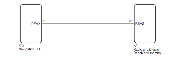
WIRING DIAGRAM
PROCEDURE
| 1. |
CHECK HARNESS AND CONNECTOR (RADIO AND DISPLAY RECEIVER ASSEMBLY - NAVIGATION ECU) |
(a) Disconnect the K1 radio and display receiver assembly connector.
(b) Disconnect the K17 navigation ECU connector.
(c) Measure the resistance according to the value(s) in the table below.
Standard Resistance:
|
Tester Connection | Condition |
Specified Condition |
|---|---|---|
|
K1-28 (REV2) - K17-19 (REV2) |
Always | Below 1 Ω |
|
K1-28 (REV2) or K17-19 (REV2) - Body ground |
Always | 10 kΩ or higher |
| OK | .gif) | PROCEED TO NEXT SUSPECTED AREA SHOWN IN PROBLEM SYMPTOMS TABLE
|
.gif)
| NG | | REPAIR OR REPLACE HARNESS OR CONNECTOR |
READ NEXT:
 Start Up Signal Circuit between Radio Receiver Assembly and Navigation ECU
DESCRIPTION This circuit includes the navigation ECU and radio and display receiver assembly. WIRING DIAGRAM
PROCEDURE
1.
CHECK HARNESS AND CONNECTOR (RADIO AND DISPLAY RECEIVER ASSEMBLY
Voice Guidance Circuit between Radio Receiver and Stereo Component Amplifier
DESCRIPTION Using this circuit, the radio and display receiver assembly sends signals to the stereo component amplifier assembly. WIRING DIAGRAM
PROCEDURE
1.
CHECK HARNESS AND CONNECTOR
Microphone Circuit
DESCRIPTION
w/o Manual (SOS) Switch:
The radio and display receiver assembly, roof console box sub-assembly and telephone microphone assembly are connected to each other using the microphone co
SEE MORE:
Electric Parking Brake Switch
ComponentsCOMPONENTS ILLUSTRATION
*1 ELECTRIC PARKING BRAKE SWITCH ASSEMBLY
- - RemovalREMOVAL PROCEDURE
1. PRECAUTION Click here
2. REMOVE REAR UPPER CONSOLE PANEL SUB-ASSEMBLY Click here
3. REMOVE ELECTRIC PARKING BRAKE SWITCH ASSEMBLY
(a) Disengage the c
Installation
INSTALLATION CAUTION / NOTICE / HINT
HINT:
Use the same procedure for the RH side and LH side.
The following procedure is for the LH side.
PROCEDURE 1. INSTALL HEADLIGHT ASSEMBLY
(a) Connect each connector. (b) for Bulb Type Turn Signal Light:
(1) Engage the clamp. (c) Engag
© 2023-2026 Copyright www.tocamry.com
