Toyota Camry (XV70): Voice Guidance Circuit between Radio Receiver and Stereo Component Amplifier
DESCRIPTION
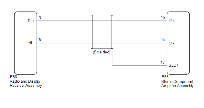
Using this circuit, the radio and display receiver assembly sends signals to the stereo component amplifier assembly.
WIRING DIAGRAM
PROCEDURE
| 1. |
CHECK HARNESS AND CONNECTOR (RADIO AND DISPLAY RECEIVER ASSEMBLY - STEREO COMPONENT AMPLIFIER ASSEMBLY) |
(a) Disconnect the K4 radio and display receiver assembly connector.
(b) Disconnect the K10 stereo component amplifier assembly connector.
(c) Measure the resistance according to the value(s) in the table below.
Standard Resistance:
|
Tester connection | Condition |
Specified condition |
|---|---|---|
|
K4-3 (RL+) - K10-15 (II1+) |
Always | Below 1 Ω |
|
K4-8 (RL-) - K10-14 (II1-) |
Always | Below 1 Ω |
|
K10-18 (SLD1) - Body ground |
Always | 10 kΩ or higher |
|
K4-3 (RL+) or K10-15 (II1+) - Body ground |
Always | 10 kΩ or higher |
|
K4-8 (RL-) or K10-14 (II1-) - Body ground |
Always | 10 kΩ or higher |
| OK | .gif) | PROCEED TO NEXT SUSPECTED AREA SHOWN IN PROBLEM SYMPTOMS TABLE
|
.gif)
| NG | | REPAIR OR REPLACE HARNESS OR CONNECTOR |
READ NEXT:
 Microphone Circuit
DESCRIPTION
w/o Manual (SOS) Switch:
The radio and display receiver assembly, roof console box sub-assembly and telephone microphone assembly are connected to each other using the microphone co
Radio Receiver Power Source Circuit
DESCRIPTION This is the power source circuit to operate the radio and display receiver assembly. WIRING DIAGRAM
CAUTION / NOTICE / HINT
NOTICE: Inspect the fuses for circuits related to this syst
SEE MORE:
Sliding Roof ECU Communication Stop (B1273)
DESCRIPTION This DTC is stored when LIN communication between the sliding roof ECU (sliding roof drive gear sub-assembly)*1 or sliding roof ECU (sliding roof drive gear assembly)*2 and main body ECU (multiplex network body ECU) stops for 10 seconds or more.
DTC No. Detection Item
DTC De
Operation Method
OPERATION METHOD PROCEDURE 1. PRECAUTION
Click here 2. REMOVE REAR SEAT CUSHION ASSEMBLY
Click here
3. REMOVE REAR SEAT CUSHION LOCK HOOK
Click here
4. PARKING BRAKE FORCED RELEASE
CAUTION: Work on a level surface to ensure safety.
NOTICE:
To release the parking brake, foll
