Toyota Camry (XV70): Radio Receiver Power Source Circuit
DESCRIPTION
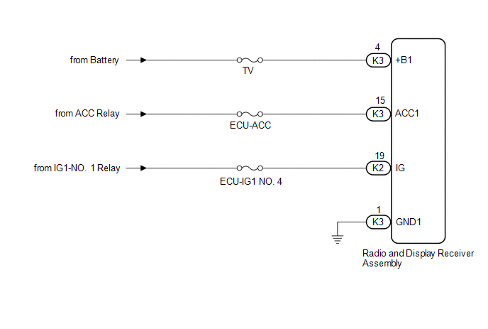
This is the power source circuit to operate the radio and display receiver assembly.
WIRING DIAGRAM
CAUTION / NOTICE / HINT
NOTICE:
Inspect the fuses for circuits related to this system before performing the following procedure.
PROCEDURE
| 1. |
CHECK HARNESS AND CONNECTOR (RADIO AND DISPLAY RECEIVER ASSEMBLY POWER SOURCE) |
(a) Disconnect the K3 and K2 radio and display receiver assembly connectors.
(b) Measure the resistance according to the value(s) in the table below.
Standard Resistance:
|
Tester Connection | Condition |
Specified Condition |
|---|---|---|
|
K3-1 (GND1) - Body ground |
Always | Below 1 Ω |
(c) Measure the voltage according to the value(s) in the table below.
Standard Voltage:
|
Tester Connection | Condition |
Specified Condition |
|---|---|---|
|
K3-4 (+B1) - K3-1 (GND1) |
Always | 11 to 14 V |
|
K3-15 (ACC1) - K3-1 (GND1) |
Engine switch on (ACC) |
11 to 14 V |
|
K2-19 (IG) - K3-1 (GND1) |
Engine switch on (IG) |
11 to 14 V |
| OK | .gif) | PROCEED TO NEXT SUSPECTED AREA SHOWN IN PROBLEM SYMPTOMS TABLE
|
.gif)
| NG | | REPAIR OR REPLACE HARNESS OR CONNECTOR |
READ NEXT:
 Blind Spot Monitor Sensor
ComponentsCOMPONENTS ILLUSTRATION
*1 BLIND SPOT MONITOR SENSOR LH
*2 BLIND SPOT MONITOR SENSOR RH
*3 REAR BUMPER ASSEMBLY
- -
N*m (kgf*cm, ft.*lbf)
SEE MORE:
Installation
INSTALLATION CAUTION / NOTICE / HINT
HINT:
Use the same procedure for the RH side and LH side.
The following procedure is for the LH side.
PROCEDURE 1. INSTALL REAR AXLE HUB AND BEARING ASSEMBLY
(a) Install the rear axle hub and bearing assembly and rear disc brake dust cover sub
Components
COMPONENTS ILLUSTRATION
*1 FRONT WHEEL OPENING EXTENSION PAD LH
*2 FRONT WHEEL OPENING EXTENSION PAD RH
*3 NO. 1 ENGINE UNDER COVER
- -
N*m (kgf*cm, ft.*lbf): Specified torque
- - ILLUSTRATION
*1 REAR ENGINE UNDER COVER LH
