Toyota Camry (XV70): Blind Spot Monitor Sensor
Components
COMPONENTS
ILLUSTRATION
|
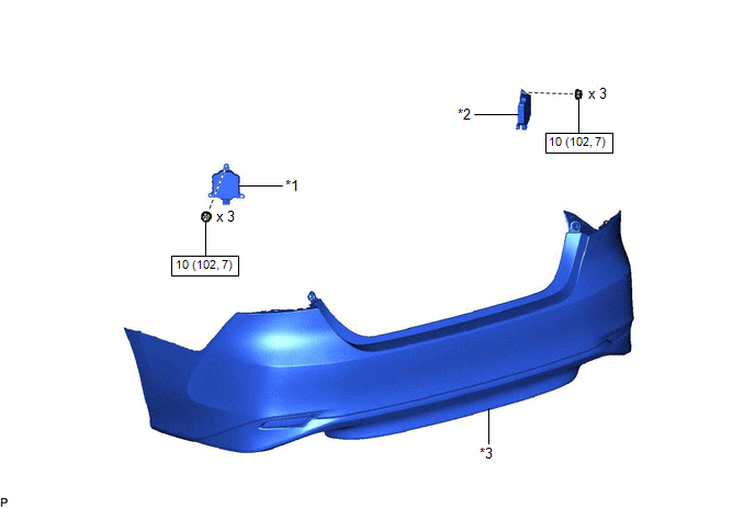
*1 | BLIND SPOT MONITOR SENSOR LH |
*2 | BLIND SPOT MONITOR SENSOR RH |
|
*3 | REAR BUMPER ASSEMBLY |
- | - |
.png) |
N*m (kgf*cm, ft.*lbf) : Specified torque |
- | - |
Removal
REMOVAL
CAUTION / NOTICE / HINT
The necessary procedures (adjustment, calibration, initialization, or registration) that must be performed after parts are removed and installed, or replaced during blind spot monitor sensor removal/installation are shown below.
Necessary Procedure After Parts Removed/Installed/Replaced|
Replaced Part or Performed Procedure |
Necessary Procedure | Effect/Inoperative Function when Necessary Procedure not Performed |
Link |
|---|---|---|---|
| Blind spot monitor sensor |
Blind spot monitor beam axis adjustment |
|
|
|
Rear bumper assembly (w/ Parking Support Brake System) |
|
|
|
PROCEDURE
1. REMOVE REAR BUMPER ASSEMBLY
Click here
.gif)
2. REMOVE BLIND SPOT MONITOR SENSOR LH
| (a) Disconnect the connector. |
|
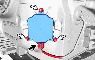
(b) Remove the 3 nuts and blind spot monitor sensor LH.
NOTICE:
Replace the blind spot monitor sensor LH if it has been dropped or subjected to a severe impact.
3. REMOVE BLIND SPOT MONITOR SENSOR RH
| (a) Disconnect the connector. |
|
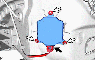
(b) Remove the 3 nuts and blind spot monitor sensor RH.
NOTICE:
Replace the blind spot monitor sensor RH if it has been dropped or subjected to a severe impact.
Installation
INSTALLATION
CAUTION / NOTICE / HINT
NOTICE:
- Avoid any impact to the blind spot monitor sensor.
- Do not drop the blind spot monitor sensor. If it is dropped, replace it with a new one.
HINT:
- The blind spot monitor beam axis confirmation is performed to confirm whether the sensor beam axis is correct, and to adjust the beam axis by using a reflector.
- The blind spot monitor sensor installation condition inspection is performed to confirm whether the sensor is perpendicular to the floor surface (+/-2.2
READ NEXT:
 Precaution
PRECAUTION PRECAUTION FOR DISCONNECTING CABLE FROM NEGATIVE BATTERY TERMINAL
NOTICE: When disconnecting the cable from the negative (-) battery terminal, initialize the following systems after the c
Parts Location
PARTS LOCATION ILLUSTRATION
*1 OUTER REAR VIEW MIRROR ASSEMBLY WITH COVER RH
*2 OUTER REAR VIEW MIRROR ASSEMBLY WITH COVER LH
*3 BRAKE ACTUATOR ASSEMBLY - SKID CONTROL EC
SEE MORE:
Components
COMPONENTS ILLUSTRATION
*1 FRONT FENDER APRON SEAL LH
*2 FRONT FENDER APRON SEAL RH
*3 FRONT LOWER BUMPER ABSORBER
*4 FRONT WHEEL OPENING EXTENSION PAD LH
*5 FRONT WHEEL OPENING EXTENSION PAD RH
*6 NO. 1 ENGINE UNDER COVER
*7 REAR ENG
Inspection
INSPECTION PROCEDURE 1. INSPECT FUEL INJECTOR ASSEMBLY
(a) Check the resistance.
(1) Measure the resistance according to the value(s) in the table below.
Standard Resistance:
Tester Connection Condition
Specified Condition 1 - 2
20°C (68°F) 11.6 to 12.4 ]
