Toyota Camry (XV70): Components
COMPONENTS
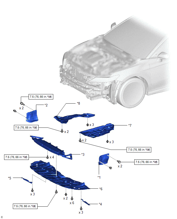
ILLUSTRATION
|
*1 | FRONT FENDER APRON SEAL LH |
*2 | FRONT FENDER APRON SEAL RH |
|
*3 | FRONT LOWER BUMPER ABSORBER |
*4 | FRONT WHEEL OPENING EXTENSION PAD LH |
|
*5 | FRONT WHEEL OPENING EXTENSION PAD RH |
*6 | NO. 1 ENGINE UNDER COVER |
|
*7 | REAR ENGINE UNDER COVER LH |
*8 | REAR ENGINE UNDER COVER RH |
.png) |
N*m (kgf*cm, ft.*lbf): Specified torque |
- | - |
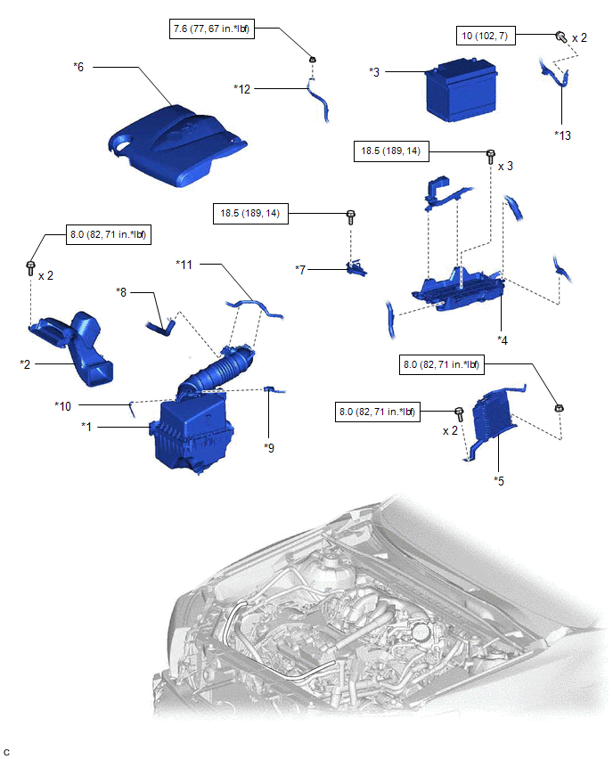
ILLUSTRATION
|
*1 | AIR CLEANER ASSEMBLY WITH AIR CLEANER HOSE |
*2 | INLET AIR CLEANER ASSEMBLY |
|
*3 | BATTERY |
*4 | BATTERY CLAMP SUB-ASSEMBLY |
|
*5 | ECM |
*6 | V-BANK COVER SUB-ASSEMBLY |
|
*7 | NO. 2 BATTERY CLAMP |
*8 | NO. 2 VENTILATION HOSE |
|
*9 | MASS AIR FLOW METER SUB-ASSEMBLY CONNECTOR |
*10 | VACUUM HOSE |
|
*11 | NO. 1 FUEL VAPOR FEED HOSE |
*12 | ENGINE ROOM MAIN WIRE |
|
*13 | EARTH WIRE |
- | - |
|
|
N*m (kgf*cm, ft.*lbf): Specified torque |
- | - |
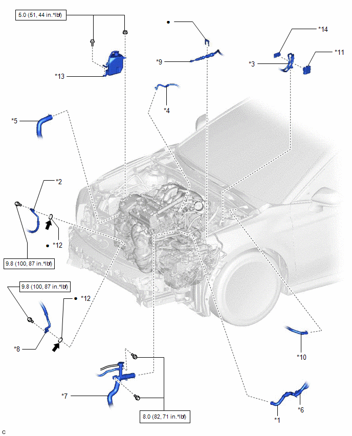
ILLUSTRATION
|
*1 | INLET HEATER WATER HOSE |
*2 | NO. 1 COOLER REFRIGERANT DISCHARGE HOSE SUB-ASSEMBLY |
|
*3 | NO. 1 FUEL HOSE |
*4 | NO. 1 FUEL VAPOR FEED HOSE |
|
*5 | NO. 2 RADIATOR HOSE |
*6 | OUTLET HEATER WATER HOSE A |
|
*7 | RADIATOR HOSE SUB-ASSEMBLY |
*8 | SUCTION HOSE SUB-ASSEMBLY |
|
*9 | TRANSMISSION CONTROL CABLE ASSEMBLY |
*10 | UNION TO CHECK VALVE HOSE |
|
*11 | EFI FUEL PIPE CLAMP |
*12 | O-RING |
|
*13 | RADIATOR RESERVE TANK ASSEMBLY |
- | - |
|
|
N*m (kgf*cm, ft.*lbf): Specified torque |
● | Non-reusable part |
.png) |
Compressor oil ND-OIL 12 or equivalent |
- | - |
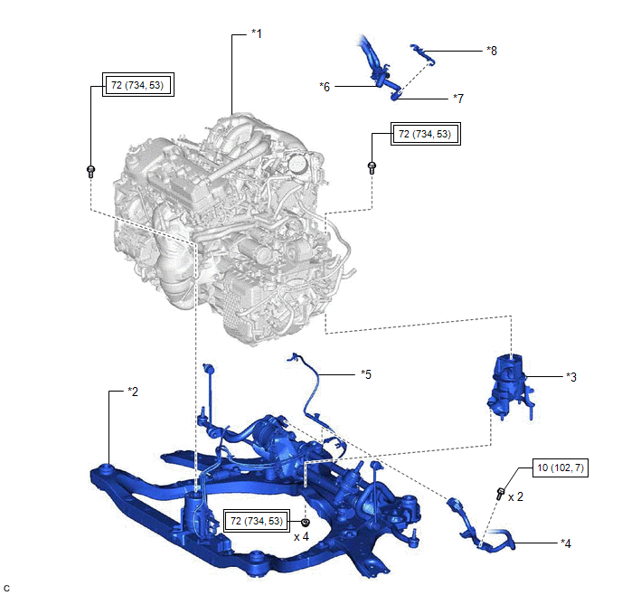
ILLUSTRATION
|
*1 | ENGINE ASSEMBLY WITH TRANSAXLE |
*2 | FRONT FRAME ASSEMBLY |
|
*3 | REAR ENGINE MOUNTING INSULATOR |
*4 | WIRE HARNESS |
|
*5 | VACUUM HOSE |
*6 | NO. 1 WATER BY-PASS HOSE |
|
*7 | WATER BY-PASS HOSE ASSEMBLY |
*8 | TRANSMISSION BREATHER CLAMP |
.png) |
Tightening torque for "Major areas involving basic vehicle performance such as moving/turning/stopping": N*m (kgf*cm, ft.*lbf) |
|
N*m (kgf*cm, ft.*lbf): Specified torque |
ILLUSTRATION
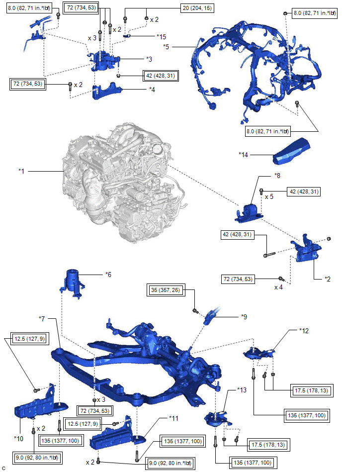
|
*1 | ENGINE ASSEMBLY WITH TRANSAXLE |
*2 | ENGINE MOUNTING BRACKET SUB-ASSEMBLY LH |
|
*3 | ENGINE MOUNTING INSULATOR SUB-ASSEMBLY RH |
*4 | ENGINE MOUNTING SPACER |
|
*5 | ENGINE WIRE |
*6 | FRONT ENGINE MOUNTING INSULATOR |
|
*7 | FRONT FRAME ASSEMBLY |
*8 | REAR NO. 2 ENGINE MOUNTING INSULATOR |
|
*9 | STEERING INTERMEDIATE SHAFT ASSEMBLY |
*10 | FRONT BUMPER EXTENSION SUB-ASSEMBLY RH |
|
*11 | FRONT BUMPER EXTENSION SUB-ASSEMBLY LH |
*12 | FRONT SUSPENSION MEMBER BRACKET SUB-ASSEMBLY RH |
|
*13 | FRONT SUSPENSION MEMBER BRACKET SUB-ASSEMBLY LH |
*14 | NO. 2 RELAY BLOCK COVER |
|
*15 | NO. 2 ENGINE MOUNTING STAY RH |
- | - |
|
|
Tightening torque for "Major areas involving basic vehicle performance such as moving/turning/stopping": N*m (kgf*cm, ft.*lbf) |
|
N*m (kgf*cm, ft.*lbf): Specified torque |
ILLUSTRATION
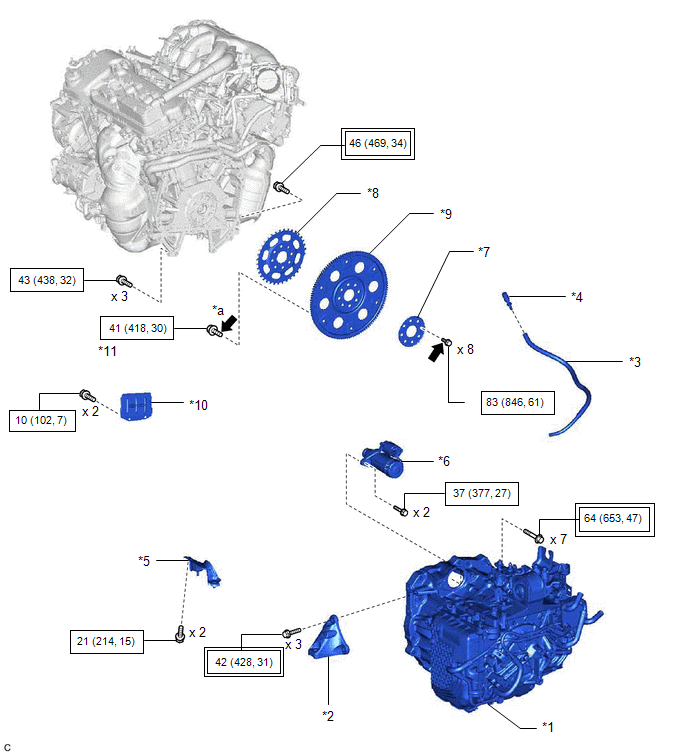
|
*1 | AUTOMATIC TRANSAXLE ASSEMBLY |
*2 | FRONT ENGINE MOUNTING BRACKET |
|
*3 | BREATHER PLUG HOSE |
*4 | BREATHER PLUG SUB-ASSEMBLY |
|
*5 | NO. 1 EXHAUST PIPE SUPPORT BRACKET (for Upper Side) |
*6 | STARTER ASSEMBLY |
|
*7 | REAR DRIVE PLATE SPACER |
*8 | NO. 1 CRANKSHAFT POSITION SENSOR PLATE |
|
*9 | DRIVE PLATE AND RING GEAR SUB-ASSEMBLY |
*10 | FLYWHEEL HOUSING UNDER COVER |
|
*11 | DRIVE PLATE AND TORQUE CONVERTER ASSEMBLY SETTING BOLT |
- | - |
|
*a | BLACK COLOR: x 1 SILVER COLOR: x 5 | - |
- |
|
|
Tightening torque for "Major areas involving basic vehicle performance such as moving/turning/stopping": N*m (kgf*cm, ft.*lbf) |
|
N*m (kgf*cm, ft.*lbf): Specified torque |
|
|
Adhesive 1324 | ★ |
Precoated part |
READ NEXT:
 Removal
REMOVAL CAUTION / NOTICE / HINT
The necessary procedures (adjustment, calibration, initialization, or registration) that must be performed after parts are removed and installed, or replaced during e
Installation
INSTALLATION CAUTION / NOTICE / HINT
CAUTION:
The engine assembly with transaxle is very heavy. Be sure to follow the procedure described in the repair manual, or the engine lifter may suddenly
SEE MORE:
Brake Line
PrecautionPRECAUTION
TROUBLESHOOTING PRECAUTION
NOTICE:
Since the brake lines are critical safety related parts, be sure to disassemble and inspect the components if a brake fluid leak is found. If any abnormalities are found, replace the component with a new one.
When removing brake co
Reassembly
REASSEMBLY PROCEDURE 1. INSTALL ROOF WIND DEFLECTOR PANEL SUB-ASSEMBLY
(a) Move the roof wind deflector panel sub-assembly in the direction indicated by the arrow (1) shown in the illustration to engage the 2 guides and install the roof wind deflector panel sub-assembly.
*a Guide
