Toyota Camry (XV70): Brake Line
Precaution
PRECAUTION
TROUBLESHOOTING PRECAUTION
NOTICE:
- Since the brake lines are critical safety related parts, be sure to disassemble and inspect the components if a brake fluid leak is found. If any abnormalities are found, replace the component with a new one.
- When removing brake components, cover the brake line connections to prevent foreign matter such as dust or dirt from entering the lines.
- Do not allow brake fluid on any painted vehicle body surface. If brake fluid leaks onto any painted surface, immediately wash it off.
- Do not damage or deform the brake lines during the removal and installation procedures.
- When installing a brake line or flexible hose, ensure that they are free from twists or kinks.
- Do not deform the bracket or the vehicle body when connecting a brake line and flexible hose.
- If the metal end of a flexible hose does not fit into the groove on the bracket, twist the hose slightly to insert it.
- Flexible hoses must be kept free from shock absorber oil, grease, etc.
- When installing a brake line to a plastic clamp, ensure that the brake line is not loose or pinched.
- Do not reuse any clips or plastic clamps removed from a flexible hose.
- After installing a brake line or flexible hose, ensure that they do not interfere with any other components or the vehicle body.
DISCONNECTING AND CONNECTING FLEXIBLE HOSE AND BRAKE LINE
(a) Disconnecting:
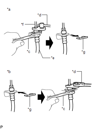
|
*a | Disconnecting |
|
*b | Connecting |
|
*c | Hold |
|
*d | Turn |
|
*e | Flexible Hose |
|
*f | Brake Line |
|
*g | Clip |
(1) Hold the flexible hose with a wrench and disconnect the brake line using a union nut wrench without deforming the brake line.
(2) Remove the clip and disconnect the flexible hose.
(b) Connecting:
(1) Secure the flexible hose with a new clip. Be sure to securely install the clip.
(2) Connect the brake line using a union nut wrench without deforming the brake line.
CONNECTING BRAKE LINE AND WAY
(a) While supporting the way to prevent deformation of the brake line, connect the brake line to the way with a union nut wrench.
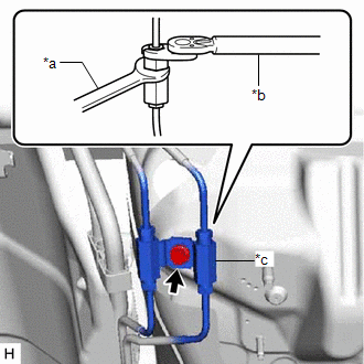
|
*a | Hold |
|
*b | Turn |
|
*c | Way |
(b) While supporting the way to prevent deformation of the brake line, install the bolt to secure the way to the vehicle body.
System Diagram
SYSTEM DIAGRAM
HINT:
See the layout drawing to confirm the locations and tightening torque of flexible hoses and brake lines.
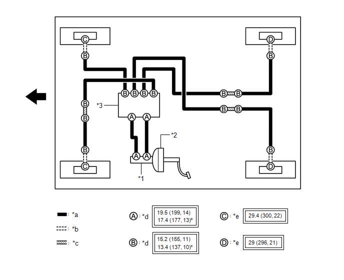
|
*1 | Brake Master Cylinder Sub-assembly |
*2 | Brake Booster Assembly |
|
*3 | Brake Actuator Assembly |
- | - |
|
*a | Brake Line |
*b | Flexible Hose |
|
*c | Brake Tube Way |
*d | Union Nut |
|
*e | Union Bolt |
- | - |
.png) |
Tightening torque for "Major areas involving basic vehicle performance such as moving/turning/stopping" : N*m (kgf*cm, ft.*lbf) |
* | For use with a union nut wrench |
.png) |
Front | - |
- |
READ NEXT:
 Components
COMPONENTS ILLUSTRATION
*1 BRAKE MASTER CYLINDER O-RING
*2 BRAKE MASTER CYLINDER SUB-ASSEMBLY
*3 BRAKE LINE
*4 CONNECTOR
*5 BRAKE BOOSTER ASSEMBLY
Removal
REMOVAL CAUTION / NOTICE / HINT
The necessary procedures (adjustment, calibration, initialization or registration) that must be performed after parts are removed and installed, or replaced during br
SEE MORE:
Tire Pressure Monitor ECU Communication Stop Mode
DESCRIPTION
Detection Item Symptom
Trouble Area Tire Pressure Monitor ECU Communication Stop Mode
Any of the following conditions are met:
Communication stop for "Tire Pressure" is indicated on the "Communication Bus Check" screen of the Techstream.
Click here
Precaution
PRECAUTION PRECAUTION FOR DISCONNECTING CABLE FROM NEGATIVE BATTERY TERMINAL
NOTICE: When disconnecting the cable from the negative (-) battery terminal, initialize the following systems after the cable is reconnected.
System Name See Procedure
Lane Tracing Assist System
