Toyota Camry (XV70): Reassembly
REASSEMBLY
PROCEDURE
1. INSTALL ROOF WIND DEFLECTOR PANEL SUB-ASSEMBLY
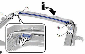
(a) Move the roof wind deflector panel sub-assembly in the direction indicated by the arrow (1) shown in the illustration to engage the 2 guides and install the roof wind deflector panel sub-assembly.
|
*a | Guide |
|
*b | Spring |
.png) |
Install in this Direction (1) |
.png) |
Install in this Direction (2) |
(b) Push each spring in the direction indicated by the arrow (2) shown in the illustration to engage the 2 springs.
NOTICE:
Make sure that the springs are securely engaged.
2. INSTALL SLIDING ROOF DRIVE CABLE SUB-ASSEMBLY
(a) Hold down the roof wind deflector panel sub-assembly.
.png)
.png) |
Hold Position |
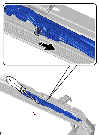
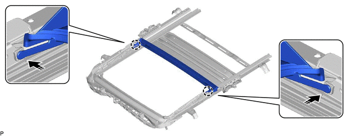
(b) Using a screwdriver, slide the sliding roof drive cable LH as shown in the illustration to install it.
|
*a | Protective Tape |
|
|
Push Position |
|
|
Install in this Direction |
HINT:
- Tape the screwdriver tip before use.
- Use the same procedure for the RH side.
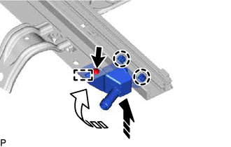
| (c) Adjust Fully Closed Position: (1) Using a screwdriver, slide the sliding roof drive cable LH in either direction and align the alignment marks as shown in the illustration. HINT: Use the same procedure for the RH side. |
|
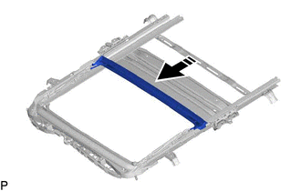
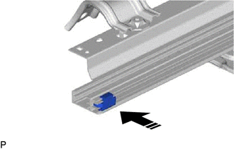
(d) Insert the rear roof drip channel into the sliding roof housing sub-assembly as shown in the illustration.
|
|
Install in this Direction |
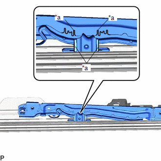
(e) Engage the 2 claws as shown in the illustration to install the rear roof drip channel.
|
|
Install in this Direction |
- | - |
3. INSTALL SUNSHADE TRIM SUB-ASSEMBLY
(a) Insert the sunshade trim sub-assembly into the sliding roof housing sub-assembly as shown in the illustration to install it.
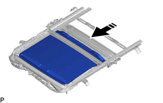
|
|
Install in this Direction |
(b) Install the rear sliding roof sunshade stopper as shown in the illustration.
|
|
Install in this Direction |
HINT:
Use the same procedure for the RH side.
(c) Move the sliding roof piece sub-assembly LH in the direction indicated by the arrow (1) shown in the illustration to engage the 2 claws.
|
|
Install in this Direction (1) |
|
|
Install in this Direction (2) |
HINT:
Use the same procedure for the RH side.
(d) Move the sliding roof piece sub-assembly LH in the direction indicated by the arrow (2) shown in the illustration to engage the guide.
HINT:
Use the same procedure for the RH side.
(e) Install the sliding roof piece sub-assembly LH with the screw.
HINT:
Use the same procedure for the RH side.
4. INSTALL SLIDING ROOF DRIVE GEAR SUB-ASSEMBLY
(a) Apply MP grease to the gear of the sliding roof drive gear sub-assembly.
| (b) Install the sliding roof drive gear sub-assembly with the 2 bolts. Torque: 5.4 N |
READ NEXT:
 Installation
INSTALLATION PROCEDURE 1. INSTALL SLIDING ROOF HOUSING ASSEMBLY
(a) Loosen the 4 bolts of the brackets of the sliding roof housing assembly.
(b) Temporarily install the sliding roof housing asse
Components
COMPONENTS ILLUSTRATION
*1 NO. 2 SLIDING ROOF SIDE GARNISH LH
*2 NO. 2 SLIDING ROOF SIDE GARNISH RH
*3 NO. 3 SLIDING ROOF SIDE GARNISH LH
*4 NO. 3 SLIDING R
SEE MORE:
Backup Battery Internal Electronic Failure (B15CC49)
DESCRIPTION This DTC is set when the DCM (telematics transceiver) detects one of the following:
The BUB (Back-Up Battery) voltage drops or the BUB (Back-Up Battery) malfunctions.
The BUB (Back-Up Battery) temperature is (temporarily) high.
DTC No. Detection Item
DTC Detect
Installation
INSTALLATION PROCEDURE 1. INSTALL FUEL PRESSURE SENSOR (FUEL DELIVERY PIPE WITH SENSOR ASSEMBLY)
HINT: Perform "Inspection After Repair" after replacing the fuel pressure sensor (fuel delivery pipe with sensor assembly).
Click here
Click here
NOTICE:
Do not remove the fuel pressu
