Toyota Camry (XV70): Parts Location
PARTS LOCATION
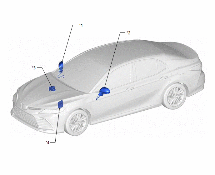
ILLUSTRATION
|
*1 | OUTER REAR VIEW MIRROR ASSEMBLY WITH COVER RH |
*2 | OUTER REAR VIEW MIRROR ASSEMBLY WITH COVER LH |
|
*3 | BRAKE ACTUATOR ASSEMBLY - SKID CONTROL ECU |
*4 | ECM |
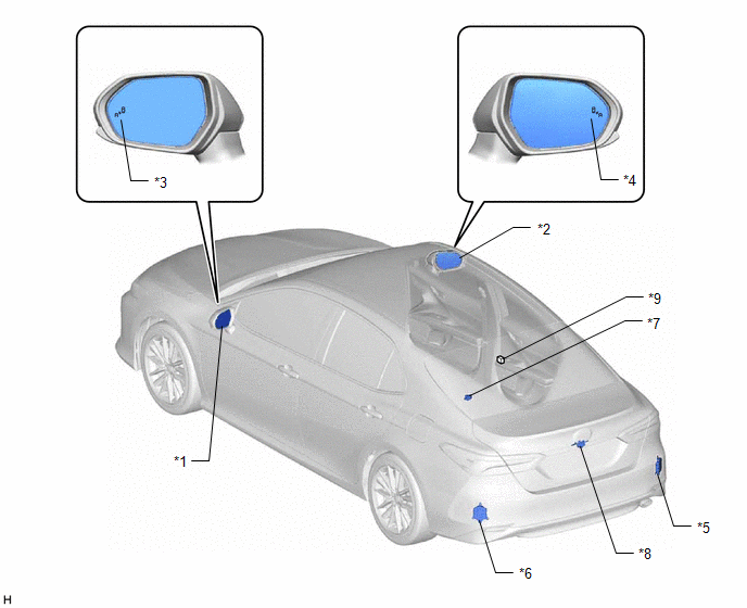
ILLUSTRATION
|
*1 | OUTER MIRROR LH |
*2 | OUTER MIRROR RH |
|
*3 | OUTER REAR VIEW MIRROR INDICATOR LH |
*4 | OUTER REAR VIEW MIRROR INDICATOR RH |
|
*5 | BLIND SPOT MONITOR SENSOR RH (MASTER) |
*6 | BLIND SPOT MONITOR SENSOR LH (SLAVE) |
|
*7 | RCTA BUZZER (BLIND SPOT MONITOR BUZZER) |
*8 | REAR TELEVISION CAMERA ASSEMBLY (w/ Parking Assist Monitor System) |
|
*9 | No. 5 JUNCTION CONNECTOR |
- | - |
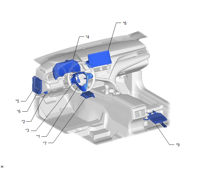
ILLUSTRATION
|
*1 | STEERING PAD SWITCH ASSEMBLY |
*2 | DLC3 |
|
*3 | STEERING SENSOR |
*4 | COMBINATION METER ASSEMBLY - MULTI-INFORMATION DISPLAY |
|
*5 | INSTRUMENT PANEL JUNCTION BLOCK ASSEMBLY - ECU-IG1 NO. 4 FUSE |
*6 | MAIN BODY ECU (MULTIPLEX NETWORK BODY ECU) |
|
*7 | AIRBAG SENSOR ASSEMBLY |
*8 | RADIO AND DISPLAY RECEIVER ASSEMBLY |
|
*9 | TELEVISION CAMERA CONTROLLER (w/ Panoramic View Monitor System) |
- | - |
READ NEXT:
 System Diagram
SYSTEM DIAGRAM
System Description
SYSTEM DESCRIPTION OPERATION OF OUTER REAR VIEW MIRROR INDICATOR AND RCTA BUZZER (BLIND SPOT MONITOR BUZZER)
(a) Initial check (1) When the blind spot monitor system is turned on with the engine swi
How To Proceed With Troubleshooting
CAUTION / NOTICE / HINT
HINT:
Use the following procedure to troubleshoot the blind spot monitor system.
*: Use the Techstream.
PROCEDURE
1. VEHICLE BROUGHT TO WORKSHOP
SEE MORE:
Removal
REMOVAL CAUTION / NOTICE / HINT
NOTICE:
Immediately after installing the brake pads, the braking performance may be reduced. Always perform a road test in a safe place while paying attention to the surroundings.
After replacing the rear disc brake pads, the brake pedal may feel soft due t
Removal
REMOVAL PROCEDURE 1. REMOVE NO. 1 METER HOOD CLUSTER
Click here
2. REMOVE LOWER INSTRUMENT PANEL FINISH PANEL ASSEMBLY Click here
3. REMOVE ENGINE SWITCH
(a) Disengage the 2 claws and remove the engine switch from lower instrument panel finish panel assembly.
