Toyota Camry (XV70): Air Conditioning Amplifier Communication Stop Mode
DESCRIPTION
|
Detection Item | Symptom |
Trouble Area |
|---|---|---|
| Air Conditioning Amplifier Communication Stop Mode |
Any of the following conditions are met:
|
|
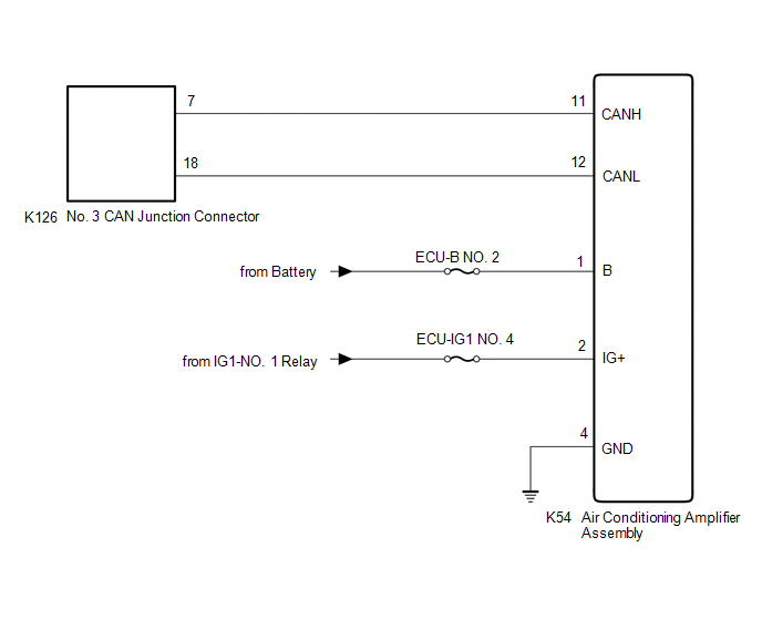
WIRING DIAGRAM
CAUTION / NOTICE / HINT
CAUTION:
When performing the confirmation driving pattern, obey all speed limits and traffic laws.
NOTICE:
- Because the order of diagnosis is important to allow correct diagnosis, make sure to begin troubleshooting using How to Proceed with Troubleshooting when CAN communication system related DTCs are output.
Click here
.gif)
- Before measuring the resistance of the CAN bus, turn the ignition switch off and leave the vehicle for 1 minute or more without operating the key or any switches, or opening or closing the doors. After that, disconnect the cable from the negative (-) battery terminal and leave the vehicle for 1 minute or more before measuring the resistance.
- After turning the ignition switch off, waiting time may be required before disconnecting the cable from the negative (-) battery terminal. Therefore, make sure to read the disconnecting the cable from the negative (-) battery terminal notices before proceeding with work.
Click here
- After performing repairs, perform the DTC check procedure and confirm that the DTCs are not output again.
DTC check procedure: Turn the ignition switch to ON and wait for 1 minute or more. Then operate the suspected malfunctioning system and drive the vehicle at 60 km/h (37 mph) or more for 5 minutes or more.
- After the repair, perform the CAN bus check and check that all the ECUs and sensors connected to the CAN communication system are displayed as normal.
Click here
- Inspect the fuses for circuits related to this system before performing the following procedure.
HINT:
- Before disconnecting related connectors for inspection, push in on each connector body to check that the connector is not loose or disconnected.
- When a connector is disconnected, check that the terminals and connector body are not cracked, deformed or corroded.
PROCEDURE
|
1. | CHECK FOR OPEN IN CAN BUS LINES (AIR CONDITIONING AMPLIFIER ASSEMBLY BRANCH LINE) |
(a) Disconnect the cable from the negative (-) battery terminal.
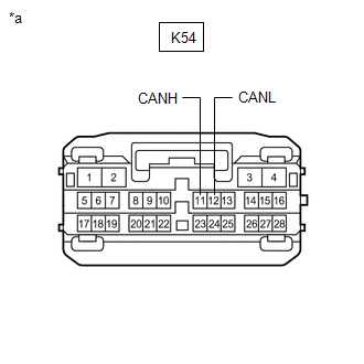
(b) Disconnect the K54 air conditioning amplifier assembly connector.
| (c) Measure the resistance according to the value(s) in the table below. Standard Resistance:
|
|
| NG | .gif) | REPAIR OR REPLACE CAN BRANCH LINES OR CONNECTOR (AIR CONDITIONING AMPLIFIER ASSEMBLY) |
|
.gif)
| 2. |
CHECK HARNESS AND CONNECTOR (POWER SOURCE CIRCUIT) |
| (a) Measure the resistance according to the value(s) in the table below. Standard Resistance:
|
|
(b) Reconnect the cable to the negative (-) battery terminal.
(c) Measure the voltage according to the value(s) in the table below.
Standard Voltage:
|
Tester Connection | Condition |
Specified Condition |
|---|---|---|
|
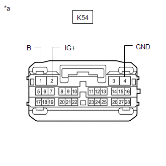
K54-1 (B) - Body ground |
Always | 11 to 14 V |
|
K54-2 (IG+) - Body ground |
Ignition switch ON | 11 to 14 V |
| OK | | REPLACE AIR CONDITIONING AMPLIFIER ASSEMBLY
|
| NG | | REPAIR OR REPLACE HARNESS OR CONNECTOR (POWER SOURCE CIRCUIT) |
READ NEXT:
 Power Steering ECU Communication Stop Mode
DESCRIPTION
Detection Item Symptom
Trouble Area Power Steering ECU Communication Stop Mode
Any of the following conditions are met:
Communication stop for "Power Steeri
Steering Angle Sensor Communication Stop Mode
DESCRIPTION
Detection Item Symptom
Trouble Area Steering Angle Sensor Communication Stop Mode
Any of the following conditions are met:
Communication stop for "Spiral ca
ECM Communication Stop Mode
DESCRIPTION
Detection Item Symptom
Trouble Area ECM Communication Stop Mode
Any of the following conditions are met:
Communication stop for "ECM (Engine)" is indicated
SEE MORE:
Cruise Control System Internal Failure (P057504,P057549)
DESCRIPTION When the ECM detects an internal malfunction, DTC P057504 or P057549 is stored.
DTC No. Detection Item
DTC Detection Condition Trouble Area
DTC Output from
P057504 Cruise Control System Internal Failure
When the dynamic radar cruise control system is o
Left Rear Wheel Speed Sensor Circuit Voltage Out of Range (C050C1C)
DESCRIPTION Refer to DTC C050C12 Click here
DTC No. Detection Item
DTC Detection Condition Trouble Area
C050C1C Left Rear Wheel Speed Sensor Circuit Voltage Out of Range
When the vehicle is being driven in a straight line at a speed of 20 km/h (12 mph) or more
