Toyota Camry (XV70): Power Steering ECU Communication Stop Mode
DESCRIPTION
|
Detection Item | Symptom |
Trouble Area |
|---|---|---|
| Power Steering ECU Communication Stop Mode |
Any of the following conditions are met:
|
|
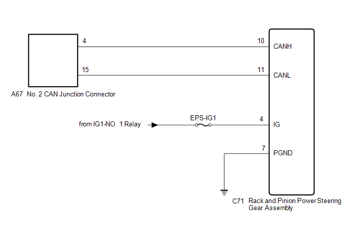
WIRING DIAGRAM
CAUTION / NOTICE / HINT
CAUTION:
When performing the confirmation driving pattern, obey all speed limits and traffic laws.
NOTICE:
- Because the order of diagnosis is important to allow correct diagnosis, make sure to begin troubleshooting using How to Proceed with Troubleshooting when CAN communication system related DTCs are output.
Click here
.gif)
- Before measuring the resistance of the CAN bus, turn the ignition switch off and leave the vehicle for 1 minute or more without operating the key or any switches, or opening or closing the doors. After that, disconnect the cable from the negative (-) battery terminal and leave the vehicle for 1 minute or more before measuring the resistance.
- After turning the ignition switch off, waiting time may be required before disconnecting the cable from the negative (-) battery terminal. Therefore, make sure to read the disconnecting the cable from the negative (-) battery terminal notices before proceeding with work.
Click here
- After performing repairs, perform the DTC check procedure and confirm that the DTCs are not output again.
DTC check procedure: Turn the ignition switch to ON and wait for 1 minute or more. Then operate the suspected malfunctioning system and drive the vehicle at 60 km/h (37 mph) or more for 5 minutes or more.
- After the repair, perform the CAN bus check and check that all the ECUs and sensors connected to the CAN communication system are displayed as normal.
Click here
- Inspect the fuses for circuits related to this system before performing the following procedure.
HINT:
- Before disconnecting related connectors for inspection, push in on each connector body to check that the connector is not loose or disconnected.
- When a connector is disconnected, check that the terminals and connector body are not cracked, deformed or corroded.
PROCEDURE
|
1. | CHECK FOR OPEN IN CAN BUS LINES (RACK AND PINION POWER STEERING GEAR ASSEMBLY BRANCH LINE) |
(a) Disconnect the cable from the negative (-) battery terminal.
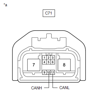
(b) Disconnect the C71 rack and pinion power steering gear assembly connector.
| (c) Measure the resistance according to the value(s) in the table below. Standard Resistance:
|
|
| NG | .gif) | REPAIR OR REPLACE CAN BRANCH LINES OR CONNECTOR (RACK AND PINION POWER STEERING GEAR ASSEMBLY) |
|
.gif)
| 2. |
CHECK HARNESS AND CONNECTOR (POWER SOURCE CIRCUIT) |
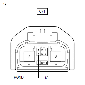
| (a) Measure the resistance according to the value(s) in the table below. Standard Resistance:
|
|
(b) Reconnect the cable to the negative (-) battery terminal.
(c) Measure the voltage according to the value(s) in the table below.
Standard Voltage:
|
Tester Connection | Condition |
Specified Condition |
|---|---|---|
|
C71-4 (IG) - Body ground |
Ignition switch ON | 11 to 14 V |
| OK | | REPLACE RACK AND PINION POWER STEERING GEAR ASSEMBLY
|
| NG | | REPAIR OR REPLACE HARNESS OR CONNECTOR (POWER SOURCE CIRCUIT) |
READ NEXT:
 Steering Angle Sensor Communication Stop Mode
DESCRIPTION
Detection Item Symptom
Trouble Area Steering Angle Sensor Communication Stop Mode
Any of the following conditions are met:
Communication stop for "Spiral ca
ECM Communication Stop Mode
DESCRIPTION
Detection Item Symptom
Trouble Area ECM Communication Stop Mode
Any of the following conditions are met:
Communication stop for "ECM (Engine)" is indicated
Main Body ECU Communication Stop Mode
DESCRIPTION
Detection Item Symptom
Trouble Area Main Body ECU Communication Stop Mode
Any of the following conditions are met:
Communication stop for "Main Body" is ind
SEE MORE:
Components
COMPONENTS ILLUSTRATION
*1 NO. 1 METER HOOD CLUSTER
*2 NO. 2 INSTRUMENT PANEL GARNISH SUB-ASSEMBLY
*3 INSTRUMENT PANEL FINISH PLATE GARNISH
*4 LOWER CENTER INSTRUMENT PANEL FINISH PANEL
*5 SHIFT LOCK RELEASE BUTTON COVER
*6 SHIFT LEVER KNOB SUB
Installation
INSTALLATION PROCEDURE 1. INSTALL STUD BOLT
HINT: If a stud bolt is deformed or its threads are damaged, replace it.
(a) Using an E8 "TORX" socket wrench, install the 2 stud bolts to the exhaust manifold assembly LH (TWC: Front Catalyst).
Torque: 19.5 N·m {199 kgf·cm, 14 ft·lbf}
