Toyota Camry (XV70): System Diagram
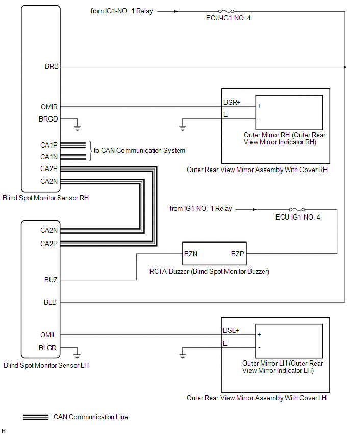
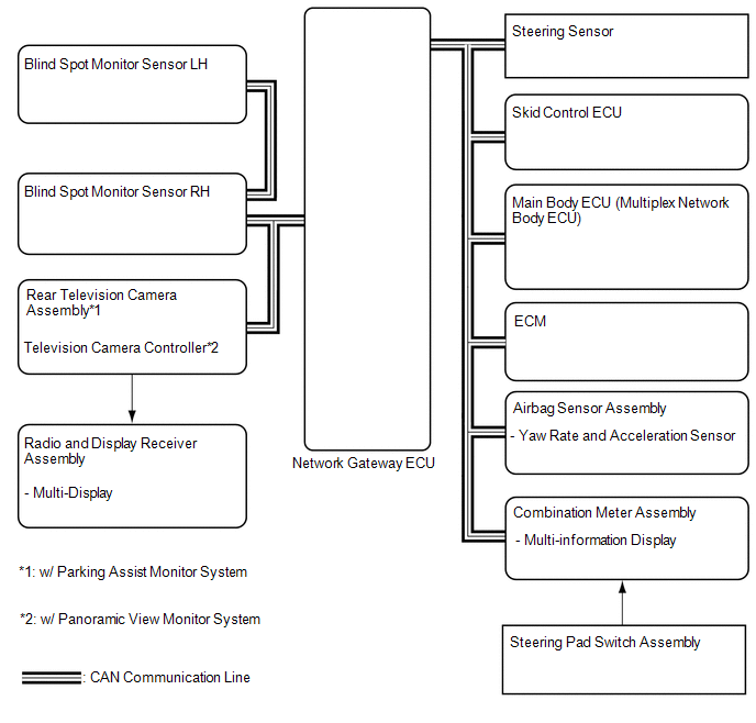
SYSTEM DIAGRAM
READ NEXT:
 System Description
SYSTEM DESCRIPTION OPERATION OF OUTER REAR VIEW MIRROR INDICATOR AND RCTA BUZZER (BLIND SPOT MONITOR BUZZER)
(a) Initial check (1) When the blind spot monitor system is turned on with the engine swi
How To Proceed With Troubleshooting
CAUTION / NOTICE / HINT
HINT:
Use the following procedure to troubleshoot the blind spot monitor system.
*: Use the Techstream.
PROCEDURE
1. VEHICLE BROUGHT TO WORKSHOP
Operation Check
OPERATION CHECK PERFORM BLIND SPOT MONITOR BEAM AXIS CONFIRMATION
HINT: The blind spot monitor beam axis confirmation is performed to confirm whether the sensor beam axis is correct, and to adjust t
SEE MORE:
Left Front Wheel Speed Sensor Signal Stuck High (C050024)
DESCRIPTION Refer to DTC C050012 Click here
DTC No. Detection Item
DTC Detection Condition Trouble Area
C050024 Left Front Wheel Speed Sensor Signal Stuck High
The speed sensor signal is not within the specified range for 5 seconds or more.
Front speed sensor
Confirm Vehicle Headunit Functionality
PROCEDURE
1. CHECK CUSTOMER'S CELLULAR PHONE COMPATIBILITY
(a) Check if the cellular phone is compatible (Refer to http://www.toyota.com/Entune/).
Result Proceed to
Cellular phone is compatible.
A Cellular phone is not compatible.
B HINT: It is impo
© 2023-2026 Copyright www.tocamry.com
