Toyota Camry (XV70): On-vehicle Inspection
ON-VEHICLE INSPECTION
CAUTION / NOTICE / HINT
The necessary procedures (adjustment, calibration, initialization or registration) that must be performed after parts are removed and installed, or replaced when repairing air leaks in the intake system are shown below.
Necessary Procedures After Parts Removed/Installed/Replaced|
Replaced Part or Performed Procedure |
Necessary Procedure | Effect/Inoperative Function when Necessary Procedure not Performed |
Link |
|---|---|---|---|
| Air leak from intake system is repaired |
Inspection After Repair |
|
|
PROCEDURE
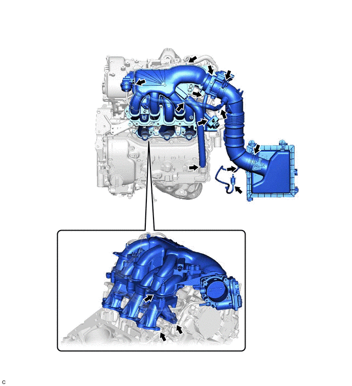
1. INSPECT INTAKE SYSTEM
CAUTION:
To prevent injury due to contact with an operating V-ribbed belt or cooling fan, keep your hands and clothing away from the V-ribbed belt and cooling fans when working in the engine compartment with the engine running or the engine switch on (IG).
.png)
(a) Check that there are no vacuum leaks at the points shown in the illustration.
HINT:
Perform Inspection After Repair after repairing vacuum leaks in the intake system.
Click here .gif)
2. INSPECT INTAKE AIR CONTROL VALVE (for ACIS)
(a) Connect the Techstream to the DLC3.
(b) Turn the engine switch on (IG).
(c) Turn the Techstream on.
| (d) Enter the following menus: Powertrain / Engine / Active Test / Activate the VSV for Intake Control. Powertrain > Engine > Active Test
|
|
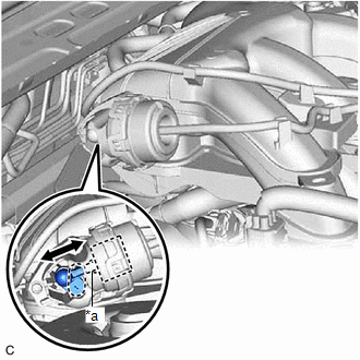
(e) When Activate the VSV for Intake Control is set to on, check that the actuator rod operates.
If the actuator rod does not operate, inspect the intake air control valve (for ACIS) and No. 1 vacuum switching valve assembly (for ACIS).
- Inspect intake air control valve (for ACIS)
Click here
- Inspect No. 1 vacuum switching valve assembly (for ACIS)
Click here
(f) When Activate the VSV for Intake Control is set to off, check that the actuator rod returns to its original position.
If the actuator rod does not return to its original position, inspect the intake air control valve (for ACIS) and No. 1 vacuum switching valve assembly (for ACIS).
- Inspect intake air control valve (for ACIS)
Click here
- Inspect No. 1 vacuum switching valve assembly (for ACIS)
Click here
3. PERFORM INITIALIZATION
(a) Perform Inspection After Repair after repairing vacuum leaks in the intake system.
Click here
READ NEXT:
 Parts Location
PARTS LOCATION ILLUSTRATION
*1 INTAKE AIR CONTROL VALVE (for ACIS)
*2 ECM
*3 ENGINE ROOM RELAY BLOCK AND JUNCTION BLOCK ASSEMBLY
- EFI NO. 1 FUSE -
-
System Diagram
SYSTEM DIAGRAM
*1 Throttle Body with Motor Assembly
*2 Intake Air Control Valve (for ACIS)
*3 Intake Air Control Valve Actuator (for ACIS)
*4 ECM
*5 Vac
On-vehicle Inspection
ON-VEHICLE INSPECTION CAUTION / NOTICE / HINT
The necessary procedures (adjustment, calibration, initialization or registration) that must be performed after parts are removed and installed, or repl
SEE MORE:
ECM/PCM Engine Off Timer Performance Signal Invalid (P261029,P261093)
DTC SUMMARY
DTC No. Detection Item
DTC Detection Condition Trouble Area
MIL Memory
Note P261029
ECM/PCM Engine Off Timer Performance Signal Invalid
ECM internal malfunction
ECM Comes on
DTC stored SAE Code: P2610
P261093 ECM/PCM En
Message Not Displayed on Multi-information Display When AUTO Function Set to ON/OFF
DESCRIPTION When the AUTO function is set to ON/OFF, a message is displayed on the multi-information display in the combination meter assembly. WIRING DIAGRAM
PROCEDURE
1.
CHECK OPERATION OF AUTO FUNCTION (a) Check that the AUTO function operates when the operating conditions are me
