Toyota Camry (XV70): Components
COMPONENTS
ILLUSTRATION

|
*A | for 7 Inch Display |
*B | for 9 Inch Display |
|
*C | w/o Manual (SOS) Switch |
*D | w/ Manual (SOS) Switch |
|
*1 | CENTER INSTRUMENT CLUSTER FINISH PANEL ASSEMBLY |
*2 | CENTER INSTRUMENT CLUSTER FINISH PANEL SUB-ASSEMBLY |
|
*3 | INSTRUMENT PANEL FINISH PLATE GARNISH |
*4 | LOWER CENTER INSTRUMENT PANEL FINISH PANEL |
|
*5 | NAVIGATION ECU WITH BRACKET |
*6 | REAR UPPER CONSOLE PANEL SUB-ASSEMBLY |
|
*7 | SHIFT LEVER KNOB SUB-ASSEMBLY |
*8 | SHIFT LOCK RELEASE BUTTON COVER |
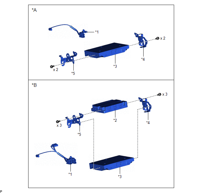
ILLUSTRATION
|
*A | w/o Manual (SOS) Switch |
*B | w/ Manual (SOS) Switch |
|
*1 | ANTENNA CORD SUB-ASSEMBLY |
*2 | DCM (TELEMATICS TRANSCEIVER) |
|
*3 | NAVIGATION ECU |
*4 | NO. 1 TELEPHONE BRACKET |
|
*5 | NO. 2 TELEPHONE BRACKET |
- | - |
READ NEXT:
 Removal
REMOVAL PROCEDURE 1. PRECAUTION
NOTICE:
When replacing the radio and display receiver assembly or navigation ECU, always replace it with a new one. If a radio and display receiver assembly or na
Installation
INSTALLATION PROCEDURE 1. PRECAUTION
NOTICE:
When replacing the radio and display receiver assembly or navigation ECU, always replace it with a new one. If a radio and display receiver assembly
SEE MORE:
Calibration
CALIBRATION
NOTICE:
Initial AWD functions such as acceleration are sometimes affected unless backup memory is cleared.
When the yaw rate and acceleration sensor (airbag sensor assembly) is replaced, Reset Memory must be performed.
RESET MEMORY (a) Turn the ignition switch off. (b) Co
Disassembly
DISASSEMBLY PROCEDURE 1. REMOVE GENERATOR PULLEY CAP
(a) Using a screwdriver, remove the generator pulley cap from the generator pulley with clutch.
NOTICE:
Do not reuse the generator pulley cap.
If the generator pulley cap is removed, replace the generator pulley cap and generat
© 2023-2026 Copyright www.tocamry.com
