Toyota Camry (XV70): Removal
REMOVAL
PROCEDURE
1. PRECAUTION
NOTICE:
- When replacing the radio and display receiver assembly or navigation ECU, always replace it with a new one. If a radio and display receiver assembly or navigation ECU which was installed to another vehicle is used, the following may occur:
- A communication malfunction DTC may be stored.
- The radio and display receiver assembly or navigation ECU may not operate normally.
- After replacing the navigation ECU, if "New software is not compatible with the system. Contact your dealer." is displayed on the multi-display, update the software of the radio and display receiver assembly.
NOTICE:
Click here .gif)
2. REMOVE AIR CONDITIONING CONTROL ASSEMBLY
Click here
3. REMOVE CENTER INSTRUMENT CLUSTER FINISH PANEL SUB-ASSEMBLY (for 7 Inch Display)
Click here
4. REMOVE CENTER INSTRUMENT CLUSTER FINISH PANEL SUB-ASSEMBLY (for 9 Inch Display)
Click here
5. REMOVE CENTER INSTRUMENT CLUSTER FINISH PANEL ASSEMBLY
Click here
6. REMOVE INSTRUMENT PANEL FINISH PLATE GARNISH
Click here
7. REMOVE LOWER CENTER INSTRUMENT PANEL FINISH PANEL
Click here
8. REMOVE SHIFT LOCK RELEASE BUTTON COVER
for UB80E:
Click here
for UA80E:
Click here
for UB80F:
Click here
9. REMOVE SHIFT LEVER KNOB SUB-ASSEMBLY
for UB80E:
Click here
for UA80E:
Click here
for UB80F:
Click here
10. REMOVE REAR UPPER CONSOLE PANEL SUB-ASSEMBLY
Click here
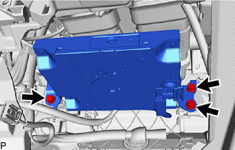
11. REMOVE NAVIGATION ECU WITH BRACKET
| (a) Disconnect each connector. |
|
| (b) Remove the 3 bolts. |
|
| (c) Disengage the 3 guides. |
|
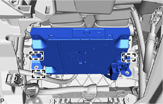
| (d) Disengage the clamp. |
|
(e) Disconnect each connector and remove the navigation ECU with bracket.
12. REMOVE ANTENNA CORD SUB-ASSEMBLY
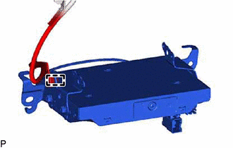
(a) w/o Manual (SOS) Switch:
| (1) Disconnect the connector. |
|
(2) Disengage the clamp to remove the antenna cord sub-assembly.
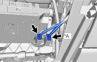
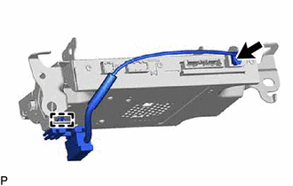
(b) w/ Manual (SOS) Switch:
| (1) Disconnect the 4 connectors. |
|
.png)
(2) Disengage the clamp to remove the antenna cord sub-assembly.
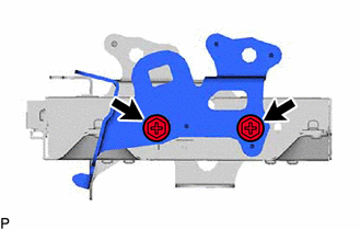
13. REMOVE NO. 2 TELEPHONE BRACKET
(a) w/o Manual (SOS) Switch:
| (1) Remove the 2 screws and No. 2 telephone bracket. |
|
(b) w/ Manual (SOS) Switch:
| (1) Remove the 3 screws and No. 2 telephone bracket. |
|
.png)
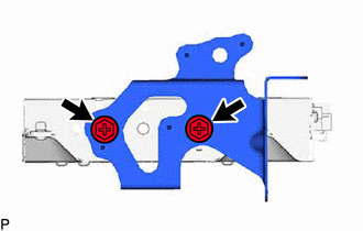
14. REMOVE NO. 1 TELEPHONE BRACKET
(a) w/o Manual (SOS) Switch:
| (1) Remove the 2 screws and No. 1 telephone bracket. |
|
(b) w/ Manual (SOS) Switch:
| (1) Remove the 3 screws and No. 1 telephone bracket. |
|
.png)
15. REMOVE DCM (TELEMATICS TRANSCEIVER) (w/ Manual (SOS) Switch)
16. REMOVE NAVIGATION ECU
READ NEXT:
 Installation
INSTALLATION PROCEDURE 1. PRECAUTION
NOTICE:
When replacing the radio and display receiver assembly or navigation ECU, always replace it with a new one. If a radio and display receiver assembly
Precaution
PRECAUTION PRECAUTION FOR DISCONNECTING CABLE FROM NEGATIVE BATTERY TERMINAL
NOTICE:
After the engine switch is turned off, the radio and display receiver assembly records various types of memor
SEE MORE:
Dtc Check / Clear
DTC CHECK / CLEAR CHECK DTC (for TIRE PRESSURE WARNING ECU AND RECEIVER)
(a) Turn the ignition switch off. (b) Connect the Techstream to the DLC3.
(c) Turn the ignition switch to ON. (d) Turn the Techstream on.
(e) Enter the following menus: Chassis / Tire Pressure Monitor / Trouble Codes. Cha
Fail-safe Chart
FAIL-SAFE CHART PROTECTION FUNCTION (a) The windshield wiper motor assembly operates the following protection functions if it detects an abnormal condition, in order to protect the wiper and washer system.
Item Protection Content
Conditions to Return to Normal Condition
Overh
