Toyota Camry (XV70): System Description
SYSTEM DESCRIPTION
OPERATION OF OUTER REAR VIEW MIRROR INDICATOR AND RCTA BUZZER (BLIND SPOT MONITOR BUZZER)
(a) Initial check
(1) When the blind spot monitor system is turned on with the engine switch on (IG), the outer rear view mirror indicators on the outer rear view mirror assembly with cover illuminate for 3 seconds.
(2) When the RCTA function is turned on with the engine switch on (IG), the outer rear view mirror indicators on the outer rear view mirror assembly with cover illuminate for 3 seconds and the RCTA buzzer (blind spot monitor buzzer) sounds for 1 second.
(3) When the engine switch is turned from off to ON with the blind spot monitor system on, the outer rear view mirror indicators on the outer rear view mirror assembly with cover illuminate for 3 seconds.
(b) Operation for each function
(1) Operation for blind spot monitor system
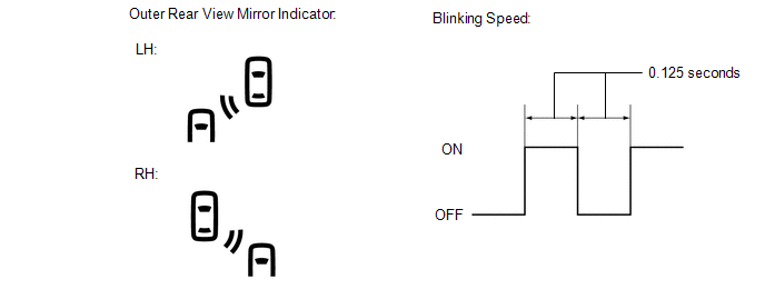
- When a sensor detects a vehicle in the blind spot area, the outer rear view mirror indicator on the outer rear view mirror assembly with cover illuminates.
- If the turn signal switch is operated while the sensor is detecting a vehicle in the detection area and the outer rear view mirror indicator on the outer rear view mirror assembly with cover is illuminated, the indicator starts blinking as shown in the illustration.
(2) Operation for RCTA function
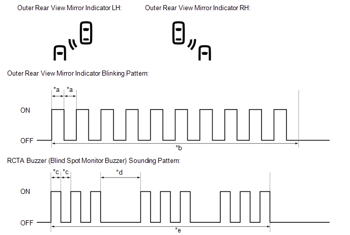
- When all of the operation conditions for the RCTA function are met, the outer rear view mirror indicators on the outer rear view mirror assembly with cover blink for 2.5 seconds and the RCTA buzzer (blind spot monitor buzzer) sounds for 2.3 seconds as shown in the illustration.
|
*a | 0.125 Seconds |
*b | 2.5 Seconds |
|
*c | 0.1 Seconds |
*d | 0.4 Seconds |
|
*e | 2.3 Seconds |
- | - |
READ NEXT:
 How To Proceed With Troubleshooting
CAUTION / NOTICE / HINT
HINT:
Use the following procedure to troubleshoot the blind spot monitor system.
*: Use the Techstream.
PROCEDURE
1. VEHICLE BROUGHT TO WORKSHOP
Operation Check
OPERATION CHECK PERFORM BLIND SPOT MONITOR BEAM AXIS CONFIRMATION
HINT: The blind spot monitor beam axis confirmation is performed to confirm whether the sensor beam axis is correct, and to adjust t
Customize Parameters
CUSTOMIZE PARAMETERS CUSTOMIZE BLIND SPOT MONITOR SYSTEM
(a) Customizing with the Techstream
NOTICE:
When the customer requests a change in a function, first make sure that the function can be
SEE MORE:
Speaker Circuit
DESCRIPTION If there is a short in a speaker circuit, the stereo component amplifier assembly detects it and stops output to the speakers.
Thus sound cannot be heard from the speakers even if there is no malfunction in the stereo component amplifier assembly, DCM (telematics transceiver)* or speak
Initialization
INITIALIZATION RESET TRANSAXLE COMPENSATION CODE
NOTICE:
If the following parts have been replaced, initialize the ECM, perform Reset Memory and Perform Road Test to Allow ECM to Learn.
ECM (When transaxle compensation code cannot be transferred.)
Transmission valve body assembly
