Toyota Camry (XV70): Components
COMPONENTS
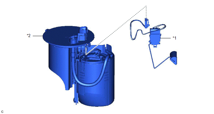
ILLUSTRATION
|
*1 | FUEL SENDER GAUGE ASSEMBLY |
*2 | FUEL SUCTION TUBE WITH PUMP AND GAUGE ASSEMBLY |
READ NEXT:
 Removal
REMOVAL CAUTION / NOTICE / HINT
The necessary procedures (adjustment, calibration, initialization or registration) that must be performed after parts are removed and installed, or replaced during fu
Inspection
INSPECTION PROCEDURE 1. INSPECT FUEL SENDER GAUGE ASSEMBLY
CAUTION: Perform the inspection in a well-ventilated area. Do not perform the inspection near an open flame.
(a) Check that the float mov
Installation
INSTALLATION PROCEDURE 1. INSTALL FUEL SENDER GAUGE ASSEMBLY
(a) Engage the claw to install the fuel sender gauge assembly to the fuel suction tube with pump and gauge assembly.
NOTICE: Be careful
SEE MORE:
System Description
SYSTEM DESCRIPTION NAVIGATION SYSTEM OUTLINE (a) Vehicle position tracking methods
It is essential that the navigation system correctly tracks the current vehicle position and displays it on the map. There are 2 methods to track the current vehicle position: autonomous (dead reckoning) and GPS* (s
Inspection
INSPECTION PROCEDURE 1. INSPECT REAR COMBINATION LIGHT LED (for Bulb Type Back-up Light)
*a Component without harness connected
(Rear Combination Light LED) (a) Apply battery voltage to the rear combination light LED and check that the lights illuminate.
OK:
Conditi
© 2023-2026 Copyright www.tocamry.com
