Toyota Camry (XV70): Inspection
INSPECTION
PROCEDURE
1. INSPECT FUEL SENDER GAUGE ASSEMBLY
CAUTION:
Perform the inspection in a well-ventilated area.
Do not perform the inspection near an open flame.
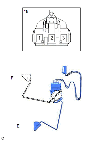
(a) Check that the float moves smoothly between F and E.
(b) Check the fuel sender gauge assembly voltage.
| (1) Apply 5 V between terminals 2 and 3. NOTICE:
HINT: If a stable power supply is not available, connect 4 nickel-metal hydride batteries (1.2 V each) or equivalent in series. |
|
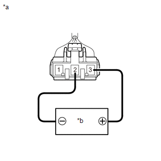
| (2) Measure the voltage according to the value(s) in the table below. Standard Voltage:
*: The output voltage changes depending on the voltage applied to the terminals. Output voltage (F) = (0.851 x Voltage applied to terminals) to (0.921 x Voltage applied to terminals) Output voltage (E) = (0.069 x Voltage applied to terminals) to (0.139 x Voltage applied to terminals) If the result is not as specified, replace the fuel sender gauge assembly. |
|
READ NEXT:
 Installation
INSTALLATION PROCEDURE 1. INSTALL FUEL SENDER GAUGE ASSEMBLY
(a) Engage the claw to install the fuel sender gauge assembly to the fuel suction tube with pump and gauge assembly.
NOTICE: Be careful
Components
COMPONENTS ILLUSTRATION
*1 FUEL SENDER GAUGE ASSEMBLY
*2 FUEL SUCTION TUBE WITH PUMP AND GAUGE ASSEMBLY
Removal
REMOVAL CAUTION / NOTICE / HINT
The necessary procedures (adjustment, calibration, initialization or registration) that must be performed after parts are removed and installed, or replaced during fu
SEE MORE:
EVAP System
RELATED DTCS
DTC No. SAE
Monitoring Item Link
P00FE00 P00FE
EVAP vent line blocked
P043E00 P043E
Reference orifice clogged (built into canister pump module)
P043F00 P043F
Reference orifice high-flow (built into canister
General maintenance
Listed below are the general maintenance items that should be
performed at the intervals specified in the "Owner's Warranty
Information Booklet" or "Owner's Manual Supplement/Scheduled
Maintenance Guide". It is recommended that any problem
you notice should be brought to the attention of your To
