Toyota Camry (XV70): Removal
REMOVAL
PROCEDURE
1. REMOVE THROTTLE BODY WITH MOTOR ASSEMBLY
Click here .gif)
2. REMOVE NO. 2 SURGE TANK STAY
Click here
3. SEPARATE ENGINE WIRE
| (a) Remove the 2 bolts and separate the engine wire. |
|
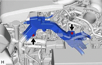
| (b) Remove the bolt and separate the earth wire. |
|
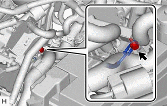
4. DISCONNECT AIR TUBE
|
(a) Slide the clip and disconnect the air tube from the vacuum pump assembly. |
|

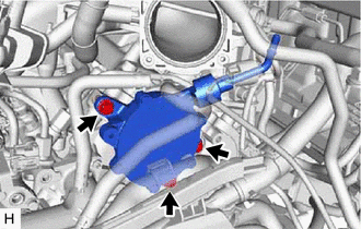
5. REMOVE VACUUM PUMP ASSEMBLY
| (a) Remove the 3 bolts and vacuum pump assembly from the engine assembly. |
|
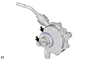
| (b) Remove the 2 O-rings from the vacuum pump assembly. |
|
READ NEXT:
 Installation
INSTALLATION PROCEDURE 1. INSTALL VACUUM PUMP ASSEMBLY
(a) Clean the vacuum pump assembly installation bolt holes in the camshaft housing sub-assembly and cylinder head sub-assembly.
(b) When usin
Components
COMPONENTS ILLUSTRATION
*1 ENGINE WIRE
*2 NO. 1 VACUUM HOSE CONNECTOR
*3 VACUUM PUMP ASSEMBLY
*4 NO. 1 VACUUM PUMP O-RING
Tightening torque for "Ma
SEE MORE:
Stop Lamp Relay Actuator Stuck Off (C13807F)
DESCRIPTION Refer to DTC C13807E. Click here
DTC No. Detection Item
DTC Detection Condition Trouble Area
C13807F Stop Lamp Relay Actuator Stuck Off
When the voltage at the +BS terminal is between 10 V or more and the stop light control relay (stop light switch asse
Rough Idling (P160500)
DESCRIPTION This DTC is stored if the combustion state of any cylinder is unstable.
Using the Techstream, the conditions present when the DTC was stored can be confirmed by referring to the freeze frame data. Freeze frame data records engine conditions when a malfunction occurs. This information c
© 2023-2026 Copyright www.tocamry.com
