Toyota Camry (XV70): Components
COMPONENTS
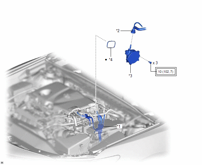
ILLUSTRATION
|
*1 | ENGINE WIRE |
*2 | NO. 1 VACUUM HOSE CONNECTOR |
|
*3 | VACUUM PUMP ASSEMBLY |
*4 | NO. 1 VACUUM PUMP O-RING |
.png) |
Tightening torque for "Major areas involving basic vehicle performance such as moving/turning/stopping": N*m (kgf*cm, ft.*lbf) |
● | Non-reusable part |
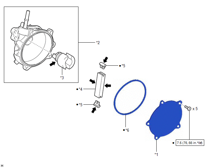
ILLUSTRATION
|
*1 | END COVER |
*2 | VACUUM PUMP HOUSING |
|
*3 | VACUUM PUMP ROTOR |
*4 | VACUUM PUMP VANE |
|
*5 | VACUUM PUMP VANE CAP |
*6 | VACUUM PUMP COVER O-RING |
.png) |
N*m (kgf*cm, ft.*lbf): Specified torque |
● | Non-reusable part |
.png) |
Engine oil | - |
- |
READ NEXT:
 On-vehicle Inspection
ON-VEHICLE INSPECTION PROCEDURE
1. OPERATION CHECK (a) Slide the clip and disconnect the union to check valve hose from the vacuum pump assembly.
(b) Connect the hose of the vacuum gauge to th
Removal
REMOVAL CAUTION / NOTICE / HINT
NOTICE: This procedure includes the removal of small-head bolts. Refer to Small-Head Bolts of Basic Repair Hint to identify the small-head bolts.
Click here
Disassembly
DISASSEMBLY PROCEDURE 1. REMOVE END COVER
(a) To prevent the coupling of the vacuum pump assembly from contacting the workbench, support the vacuum pump assembly with wooden blocks or an equival
SEE MORE:
On-vehicle Inspection
ON-VEHICLE INSPECTION CAUTION / NOTICE / HINT
HINT:
Use the same procedure for the RH side and LH side.
The following procedure is for the LH side.
PROCEDURE 1. REMOVE REAR WHEEL Click here
2. DISCONNECT NO. 2 PARKING BRAKE WIRE ASSEMBLY
Click here 3. SEPARATE REAR DISC BRAKE C
Problem Symptoms Table
PROBLEM SYMPTOMS TABLE NOTICE: Before replacing the main body ECU (multiplex network body ECU), refer to Registration.*
Click here
*: w/ Smart Key System
HINT:
Use the table below to help determine the cause of problem symptoms. If multiple suspected areas are listed
© 2023-2026 Copyright www.tocamry.com
