Toyota Camry (XV70): Removal
REMOVAL
CAUTION / NOTICE / HINT
NOTICE:
This procedure includes the removal of small-head bolts. Refer to Small-Head Bolts of Basic Repair Hint to identify the small-head bolts.
Click here .gif)
PROCEDURE
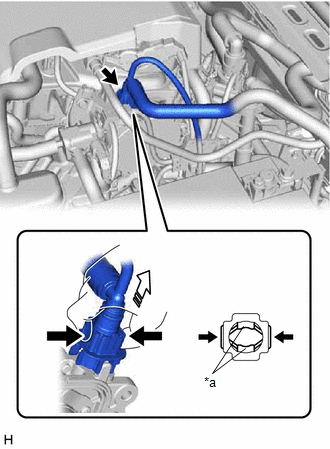
1. DISCONNECT NO. 1 VACUUM HOSE CONNECTOR
(a) Pinch the retainer of the No. 1 vacuum hose connector, and then pull the No. 1 vacuum hose connector off of the vacuum pump assembly.
NOTICE:
Be sure to disconnect the No. 1 vacuum hose connector by hand.
|
*a | Retainer |
.png) |
Pinch |
.png) |
Pull off |
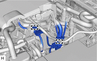
2. SEPARATE ENGINE WIRE
| (a) Disengage the 2 clamps to separate the engine wire. |
|
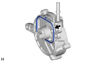
3. REMOVE VACUUM PUMP ASSEMBLY
| (a) Using an 8 mm socket wrench, remove the 3 bolts and vacuum pump assembly from the engine assembly. |
|

| (b) Remove the No. 1 vacuum pump O-ring from the vacuum pump assembly. |
|
READ NEXT:
 Disassembly
DISASSEMBLY PROCEDURE 1. REMOVE END COVER
(a) To prevent the coupling of the vacuum pump assembly from contacting the workbench, support the vacuum pump assembly with wooden blocks or an equival
Reassembly
REASSEMBLY PROCEDURE 1. CLEAN VACUUM PUMP HOUSING
(a) Clean the inside surface of the vacuum pump housing. 2. INSTALL VACUUM PUMP ROTOR
(a) Clean the vacuum pump rotor. (b) Apply engine oil to the
Installation
INSTALLATION CAUTION / NOTICE / HINT
NOTICE: This procedure includes the installation of small-head bolts. Refer to Small-Head Bolts of Basic Repair Hint to identify the small-head bolts.
Click he
SEE MORE:
Summary of functions
The multi-information display presents the driver with a variety of driving-
related data, such as the current outside temperature. The multiinformation
display can also be used to change the display settings
and other settings.
Shift position
Menu icon display area
Displays the follow
Components
COMPONENTS ILLUSTRATION
*1 VENTILATION HOSE
*2 PURGE VALVE (PURGE VSV)
*3 NO. 1 FUEL VAPOR FEED HOSE
*4 NO. 2 SURGE TANK STAY
*5 INTAKE AIR SURGE TANK ASSEMBLY
*6 AIR SURGE TANK TO INTAKE MANIFOLD GASKET
*7 VACUUM HOSE SUB-ASSEMBLY
