Toyota Camry (XV70): Installation
Toyota Camry Repair Manual XV70 (2018-2024) / Brake / Brake System (other) / Vacuum Pump (for A25a-fks) / Installation
INSTALLATION
CAUTION / NOTICE / HINT
NOTICE:
This procedure includes the installation of small-head bolts. Refer to Small-Head Bolts of Basic Repair Hint to identify the small-head bolts.
Click here .gif)
PROCEDURE
1. INSTALL VACUUM PUMP ASSEMBLY
(a) When reusing the vacuum pump assembly:
| (1) Install a new No. 1 vacuum pump O-ring to the vacuum pump assembly. |
|
.png)
| (b) Install the vacuum pump assembly so that the coupling teeth of the vacuum pump assembly and groove of the camshaft are engaged. NOTICE:
|
|
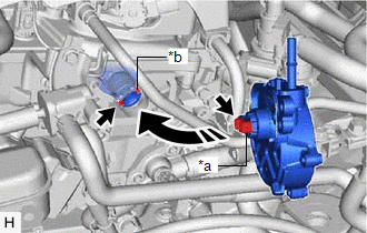
| (c) Using an 8 mm socket wrench, install the vacuum pump assembly with the 3 bolts. Torque: 10 N |
READ NEXT:
 Components
COMPONENTS ILLUSTRATION
*1 CHECK VALVE GROMMET
*2 VACUUM WARNING SWITCH ASSEMBLY
● Non-reusable part
- -
On-vehicle Inspection
ON-VEHICLE INSPECTION PROCEDURE
1. INSPECT BRAKE FLUID LEVEL IN RESERVOIR Click here
2. INSPECT BRAKE BOOSTER ASSEMBLY
Click here 3. INSPECT VACUUM WARNING SWITCH ASSEMBLY
(a) Start the en
SEE MORE:
Reassembly
REASSEMBLY CAUTION / NOTICE / HINT
HINT:
Use the same procedure for the RH side and LH side.
The following procedure is for the LH side.
PROCEDURE 1. PRECAUTION NOTICE:
After turning the ignition switch off, waiting time may be required before disconnecting the cable from the n
Removal
REMOVAL CAUTION / NOTICE / HINT
HINT:
Use the same procedure for the RH side and LH side.
The following procedure is for the LH side.
PROCEDURE 1. PRECAUTION Click here
2. RELEASE PARKING BRAKE (a) Move the shift lever to P.
(b) Turn the engine switch on (IG). (c) Operate the ele
© 2023-2026 Copyright www.tocamry.com
