Toyota Camry (XV70): Components
COMPONENTS
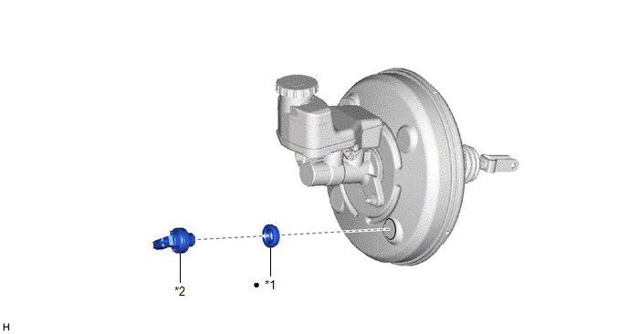
ILLUSTRATION
|
*1 | CHECK VALVE GROMMET |
*2 | VACUUM WARNING SWITCH ASSEMBLY |
|
● | Non-reusable part |
- | - |
READ NEXT:
 On-vehicle Inspection
ON-VEHICLE INSPECTION PROCEDURE
1. INSPECT BRAKE FLUID LEVEL IN RESERVOIR Click here
2. INSPECT BRAKE BOOSTER ASSEMBLY
Click here 3. INSPECT VACUUM WARNING SWITCH ASSEMBLY
(a) Start the en
Removal
REMOVAL CAUTION / NOTICE / HINT
The necessary procedures (adjustment, calibration, initialization or registration) that must be performed after parts are removed and installed, or replaced during va
Installation
INSTALLATION PROCEDURE 1. INSTALL CHECK VALVE GROMMET
(a) Install a new check valve grommet to the brake booster assembly. 2. INSTALL VACUUM WARNING SWITCH ASSEMBLY
(a) Install the vacuum warning
SEE MORE:
Removal
REMOVAL CAUTION / NOTICE / HINT
The necessary procedures (adjustment, calibration, initialization, or registration) that must be performed after parts are removed and installed, or replaced during oil pump removal/installation are shown below. Necessary Procedure After Parts Removed/Installed/Repl
Installation
INSTALLATION PROCEDURE 1. INSTALL REAR ENGINE MOUNTING INSULATOR
(a) Engage the clamp and install the vacuum hose to the rear engine mounting insulator.
(b) Install the wire harness clamp bracket to the rear engine mounting insulator with the bolt.
Torque: 10 N·m {102 kgf·cm, 7 ft·lbf}
© 2023-2026 Copyright www.tocamry.com
