Toyota Camry (XV70): 2gr-fks Spark Plug
Components
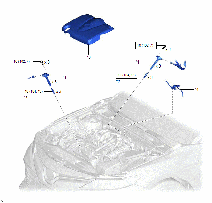
COMPONENTS
ILLUSTRATION
|
*1 | IGNITION COIL ASSEMBLY |
*2 | SPARK PLUG |
|
*3 | V-BANK COVER SUB-ASSEMBLY |
*4 | VACUUM HOSE |
.png) |
N*m (kgf*cm, ft.*lbf): Specified torque |
- | - |
Removal
REMOVAL
CAUTION / NOTICE / HINT
The necessary procedures (adjustment, calibration, initialization, or registration) that must be performed after parts are removed and installed, or replaced during spark plug removal/installation are shown below.
Necessary Procedures After Parts Removed/Installed/Replaced|
Replaced Part or Performed Procedure |
Necessary Procedure | Effect/Inoperative Function when Necessary Procedure not Performed |
Link |
|---|---|---|---|
| Inspection after repair |
|
|
PROCEDURE
1. REMOVE V-BANK COVER SUB-ASSEMBLY
Click here
.gif)
2. REMOVE IGNITION COIL ASSEMBLY
Click here
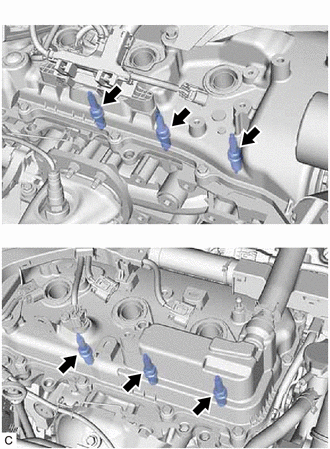
3. REMOVE SPARK PLUG
| (a) Remove the 6 spark plugs from the cylinder head sub-assembly and cylinder head LH. NOTICE: If a spark plug has been struck or dropped, replace it. HINT: Arrange the removed parts in the correct order. |
|
Installation
INSTALLATION
PROCEDURE
1. INSTALL SPARK PLUG
HINT:
Perform "Inspection After Repair" after replacing a spark plug.
Click here .gif)
(a) Install the 6 spark plugs to the cylinder head sub-assembly and cylinder head LH.
Torque:
18 N
READ NEXT:
 A25a-fks Air Cleaner Filter Element
ComponentsCOMPONENTS ILLUSTRATION
*1 AIR CLEANER CAP SUB-ASSEMBLY
*2 AIR CLEANER FILTER ELEMENT SUB-ASSEMBLY RemovalREMOVAL PROCEDURE
1. SEPARATE AIR CLEANER CAP SUB-ASSEMBLY
Components
COMPONENTS ILLUSTRATION
*1 BATTERY
*2 NEGATIVE BATTERY TERMINAL
*3 POSITIVE BATTERY TERMINAL
*4 NO. 2 BATTERY CLAMP
*5 BATTERY TERMINAL CAP
- -
SEE MORE:
Coolant
ComponentsCOMPONENTS ILLUSTRATION
*1 RADIATOR CAP SUB-ASSEMBLY
*2 RADIATOR DRAIN COCK PLUG
*3 NO. 1 ENGINE UNDER COVER
- - ReplacementREPLACEMENT CAUTION / NOTICE / HINT
CAUTION: Do not remove the radiator cap sub-assembly or radiator drain cock plug while
Washer Nozzle
ComponentsCOMPONENTS ILLUSTRATION
*1 WASHER NOZZLE SUB-ASSEMBLY
- -
● Non-reusable part
- - On-vehicle InspectionON-VEHICLE INSPECTION PROCEDURE
1. INSPECT WASHER NOZZLE SUB-ASSEMBLY (a) Operate the washer nozzle sub-assemblies and check the po
