Toyota Camry (XV70): Removal
REMOVAL
CAUTION / NOTICE / HINT
The necessary procedures (adjustment, calibration, initialization or registration) that must be performed after parts are removed and installed, or replaced during vacuum warning switch assembly removal/installation are shown below.
Necessary Procedures After Parts Removed/Installed/Replaced|
Replaced Part or Performed Procedure |
Necessary Procedure | Effect/Inoperative Function when Necessary Procedure not Performed |
Link |
|---|---|---|---|
|
Disconnect cable from negative battery terminal |
Perform steering sensor zero point calibration |
Lane tracing assist system |
|
|
Pre-collision system | |||
|
Memorize steering angle neutral point |
Parking assist monitor system |
| |
|
Panoramic view monitor system |
|
PROCEDURE
1. PRECAUTION
NOTICE:
After turning the ignition switch off, waiting time may be required before disconnecting the cable from the negative (-) battery terminal. Therefore, make sure to read the disconnecting the cable from the negative (-) battery terminal notices before proceeding with work.
Click here .gif)
2. REMOVE BATTERY
for A25A-FKS: Click here
for 2GR-FKS: Click here
3. REMOVE VACUUM WARNING SWITCH ASSEMBLY
| (a) Disconnect the connector from the vacuum warning switch assembly. |
|
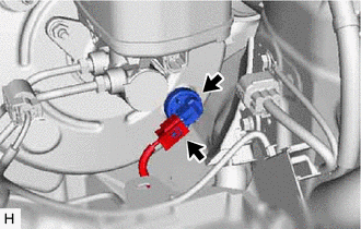
(b) Remove the vacuum warning switch assembly from the brake booster assembly.
4. REMOVE CHECK VALVE GROMMET
(a) Remove the check valve grommet from the brake booster assembly.
READ NEXT:
 Installation
INSTALLATION PROCEDURE 1. INSTALL CHECK VALVE GROMMET
(a) Install a new check valve grommet to the brake booster assembly. 2. INSTALL VACUUM WARNING SWITCH ASSEMBLY
(a) Install the vacuum warning
SEE MORE:
Front Wiper Rubber
ComponentsCOMPONENTS ILLUSTRATION
*1 FRONT WIPER BLADE
*2 WIPER RUBBER
*3 FRONT WIPER RUBBER BACKING PLATE
- - ReplacementREPLACEMENT CAUTION / NOTICE / HINT
NOTICE: Make sure to hold the front wiper arm while lifting it as lifting the front wiper ar
Components
COMPONENTS ILLUSTRATION
*1 FRONT FLEXIBLE HOSE
*2 GASKET
*3 BRAKE LINE
*4 FRONT SPEED SENSOR
*5 UNION BOLT
- -
Tightening torque for "Major areas involving basic vehicle performance such as moving/turning/stopping" : N*m (kgf*cm,
