Toyota Camry (XV70): Removal
REMOVAL
CAUTION / NOTICE / HINT
The necessary procedures (adjustment, calibration, initialization, or registration) that must be performed after parts are removed and installed, or replaced during clearance warning ECU assembly removal/installation are shown below.
Necessary Procedure After Parts Removed/Installed/Replaced|
Replaced Part or Performed Procedure |
Necessary Procedures | Effect/Inoperative Function when Necessary Procedure not Performed |
Link |
|---|---|---|---|
| Disconnect cable from negative battery terminal |
Perform steering sensor zero point calibration |
Lane Tracing Assist System |
|
|
Pre-collision System | |||
|
Memorize steering angle neutral point |
Parking Assist Monitor System |
| |
|
Panoramic View Monitor System |
| ||
|
Replacement of clearance warning ECU assembly |
|
|
|
CAUTION:
Some of these service operations affect the SRS airbag system. Read the precautionary notices concerning the SRS airbag system before servicing.
Click here .gif)
.png)
PROCEDURE
1. REMOVE LOWER NO. 2 INSTRUMENT PANEL AIRBAG ASSEMBLY
Click here
2. REMOVE LOWER INSTRUMENT PANEL SUB-ASSEMBLY
Click here
3. REMOVE ECU INTEGRATION BOX RH
Click here
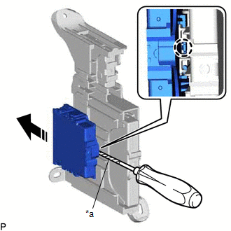
4. REMOVE CLEARANCE WARNING ECU ASSEMBLY
(a) Using a screwdriver with its tip wrapped with protective tape, disengage the claw and remove the clearance warning ECU assembly as shown in the illustration.
|
*a | Protective Tape |
.png) |
Remove in this Direction |
NOTICE:
- If the ECU integration box is deformed or damaged, replace it.
- Do not bend the claw more than necessary.
READ NEXT:
 Installation
INSTALLATION PROCEDURE 1. INSTALL CLEARANCE WARNING ECU ASSEMBLY
(a) Engage the claw to install the clearance warning ECU assembly as shown in the illustration.
Install in this Dire
Precaution
PRECAUTION PRECAUTION FOR DISCONNECTING CABLE FROM NEGATIVE BATTERY TERMINAL
NOTICE: When disconnecting the cable from the negative (-) battery terminal, initialize the following systems after the c
SEE MORE:
2gr-fks Drive Belt
ComponentsCOMPONENTS ILLUSTRATION
*1 FRONT FENDER APRON SEAL RH
*2 V-RIBBED BELT RemovalREMOVAL PROCEDURE
1. REMOVE FRONT WHEEL RH Click here
2. REMOVE FRONT FENDER APRON SEAL RH
Click here
3. REMOVE V-RIBBED BELT
(a) Release the V-ribbed belt tension
Insufficient Coolant Temperature for Closed Loop Fuel Control (P012500)
DESCRIPTION Refer to DTC P011511. Click here
DTC No. Detection Item
DTC Detection Condition Trouble Area
MIL Memory
Note P012500
Insufficient Coolant Temperature for Closed Loop Fuel Control
The engine coolant temperature does not reach the closed loop
