Toyota Camry (XV70): Installation
INSTALLATION
PROCEDURE
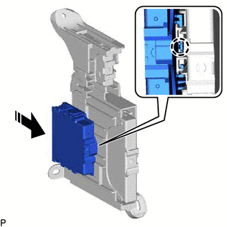
1. INSTALL CLEARANCE WARNING ECU ASSEMBLY
(a) Engage the claw to install the clearance warning ECU assembly as shown in the illustration.
.png) |
Install in this Direction |
2. INSTALL ECU INTEGRATION BOX RH
Click here .gif)
3. INSTALL LOWER INSTRUMENT PANEL SUB-ASSEMBLY
Click here
4. INSTALL LOWER NO. 2 INSTRUMENT PANEL AIRBAG ASSEMBLY
Click here
5. PERFORM CALIBRATION
Click here
SST: 09989-00020
READ NEXT:
 Precaution
PRECAUTION PRECAUTION FOR DISCONNECTING CABLE FROM NEGATIVE BATTERY TERMINAL
NOTICE: When disconnecting the cable from the negative (-) battery terminal, initialize the following systems after the c
Parts Location
PARTS LOCATION ILLUSTRATION
*1 FRONT CORNER ULTRASONIC SENSOR LH
*2 FRONT CENTER ULTRASONIC SENSOR LH
*3 FRONT CENTER ULTRASONIC SENSOR RH
*4 FRONT CORNER ULTRASO
SEE MORE:
Initialization
INITIALIZATION INITIALIZE PANORAMIC MOON ROOF SYSTEM (FOR SLIDING ROOF)
NOTICE:
When the sliding roof glass sub-assembly, sliding roof housing panel or slide roof rail sub-assembly is adjusted or removed/installed, or the sliding roof ECU (sliding roof drive gear assembly) is replaced, the
Removal
REMOVAL CAUTION / NOTICE / HINT
NOTICE: If both left and right front flexible hoses are disconnected at the same time, be sure to place an identification mark on each hose to indicate its installation position.
HINT:
Use the same procedure for the RH side and LH side.
The following proce
© 2023-2026 Copyright www.tocamry.com
