Toyota Camry (XV70): Parts Location
PARTS LOCATION
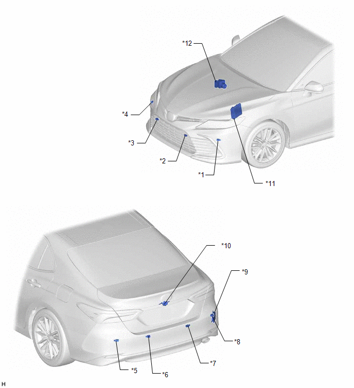
ILLUSTRATION
|
*1 | FRONT CORNER ULTRASONIC SENSOR LH |
*2 | FRONT CENTER ULTRASONIC SENSOR LH |
|
*3 | FRONT CENTER ULTRASONIC SENSOR RH |
*4 | FRONT CORNER ULTRASONIC SENSOR RH |
|
*5 | REAR CORNER ULTRASONIC SENSOR LH |
*6 | REAR CENTER ULTRASONIC SENSOR LH |
|
*7 | REAR CENTER ULTRASONIC SENSOR RH |
*8 | REAR CORNER ULTRASONIC SENSOR RH |
|
*9 | BLIND SPOT MONITOR SENSOR RH (B) |
*10 | REAR TELEVISION CAMERA ASSEMBLY |
|
*11 | ECM |
*12 | BRAKE ACTUATOR ASSEMBLY - SKID CONTROL ECU |
ILLUSTRATION

|
*1 | SPIRAL CABLE SUB-ASSEMBLY |
*2 | STEERING PAD SWITCH ASSEMBLY |
|
*3 | STEERING SENSOR |
*4 | INSTRUMENT PANEL JUNCTION BLOCK ASSEMBLY - ECU-IG1 NO. 4 FUSE |
|
*5 | MAIN BODY ECU (MULTIPLEX NETWORK BODY ECU) |
*6 | RADIO AND DISPLAY RECEIVER ASSEMBLY |
|
*7 | NO. 1 CLEARANCE WARNING BUZZER |
*8 | COMBINATION METER ASSEMBLY - MULTI-INFORMATION DISPLAY - CLEARANCE SONAR OFF INDICATOR - RCTA OFF INDICATOR |
|
*9 | CLEARANCE WARNING ECU ASSEMBLY |
*10 | TELEVISION CAMERA CONTROLLER |
|
*11 | METER MIRROR SUB-ASSEMBLY |
*12 | DLC3 |
|
*13 | AIR CONDITIONING AMPLIFIER ASSEMBLY |
*14 | AIRBAG SENSOR ASSEMBLY |
READ NEXT:
 System Diagram
SYSTEM DIAGRAM
How To Proceed With Troubleshooting
CAUTION / NOTICE / HINT
HINT:
Use the following procedure to troubleshoot the intuitive parking assist system.
*: Use the GTS.
PROCEDURE
1. VEHICLE BROUGHT TO WORKSHOP
Customize Parameters
CUSTOMIZE PARAMETERS CUSTOMIZE INTUITIVE PARKING ASSIST SYSTEM
(a) Customizing with the GTS
NOTICE:
When the customer requests a change in a function, first make sure that the function can be
SEE MORE:
Washer Nozzle
ComponentsCOMPONENTS ILLUSTRATION
*1 WASHER NOZZLE SUB-ASSEMBLY
- -
● Non-reusable part
- - On-vehicle InspectionON-VEHICLE INSPECTION PROCEDURE
1. INSPECT WASHER NOZZLE SUB-ASSEMBLY (a) Operate the washer nozzle sub-assemblies and check the po
Tire pressure warning system
Your vehicle is equipped with a tire pressure warning system that uses
tire pressure warning valve and transmitters to detect low tire inflation
pressure before serious problems arise.
Vehicles without a tire inflation pressure display function
If the tire pressure drops below a predetermined le
