Toyota Camry (XV70): System Diagram
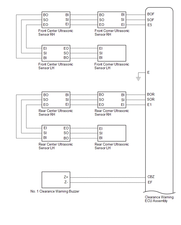
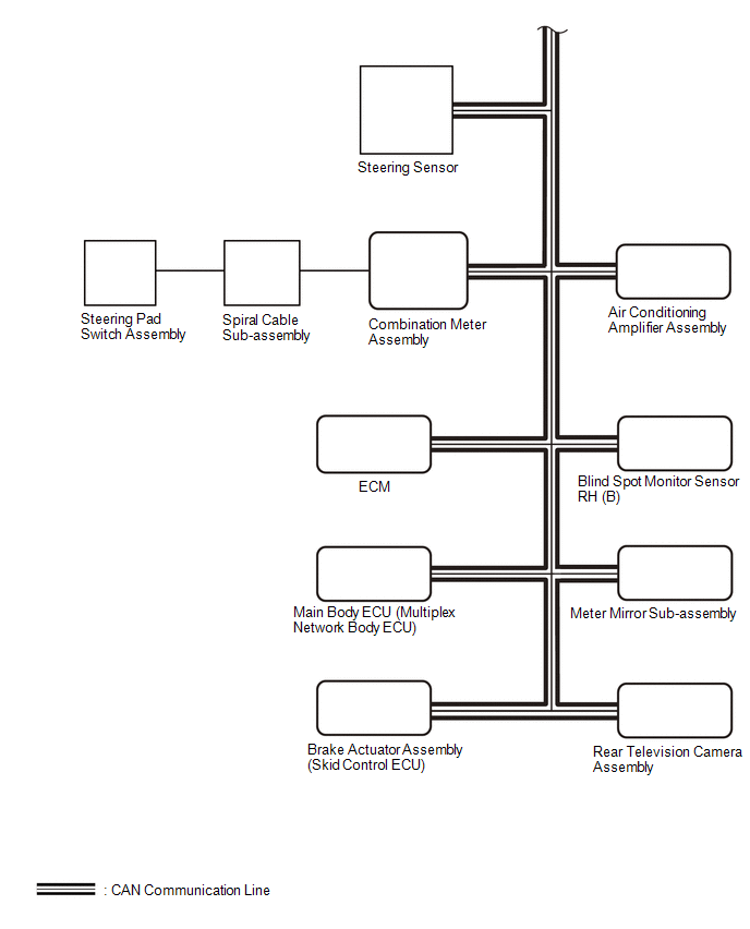
SYSTEM DIAGRAM

READ NEXT:
 How To Proceed With Troubleshooting
CAUTION / NOTICE / HINT
HINT:
Use the following procedure to troubleshoot the intuitive parking assist system.
*: Use the GTS.
PROCEDURE
1. VEHICLE BROUGHT TO WORKSHOP
Customize Parameters
CUSTOMIZE PARAMETERS CUSTOMIZE INTUITIVE PARKING ASSIST SYSTEM
(a) Customizing with the GTS
NOTICE:
When the customer requests a change in a function, first make sure that the function can be
Calibration
CALIBRATION NOTICE: When any of the following parts have been replaced, perform adjustment shown in the following table. If not, the intuitive parking assist system may not operate correctly.
ADJUST
SEE MORE:
Reassembly
REASSEMBLY CAUTION / NOTICE / HINT
HINT:
Use the same procedure for the RH side and LH side.
The following procedure is for the LH side.
PROCEDURE 1. INSTALL REAR LIGHT LENS AND BODY
2. INSTALL REAR LIGHT PACKING
(a) Install a new rear light packing.
Operation Check
OPERATION CHECK CHECK WINDOW DEFOGGER SYSTEM (a) Turn the ignition switch to ON.
(b) Check that the rear window defogger wire becomes warm by operating the rear window defogger switch of the air conditioning control assembly.
(c) When the vehicle is stopped, confirm that the window defogger sy
© 2023-2026 Copyright www.tocamry.com
