Toyota Camry (XV70): Removal
REMOVAL
CAUTION / NOTICE / HINT
The necessary procedures (adjustment, calibration, initialization, or registration) that must be performed after parts are replaced during millimeter wave radar sensor assembly removal/installation are shown below.
Necessary Procedure After Parts Removed/Installed/Replaced|
Replaced Part or Performed Procedure |
Necessary Procedure | Effect/Inoperative Function when Necessary Procedure not Performed |
Link |
|---|---|---|---|
| Millimeter wave radar sensor assembly |
Adjust millimeter wave radar sensor assembly |
| Target Adjustment (Triangle Target):
or Target Adjustment (Flat Surface Target):
or Driving Adjustment:
|
PROCEDURE
1. REMOVE COOL AIR INTAKE DUCT SEAL
Click here
.gif)
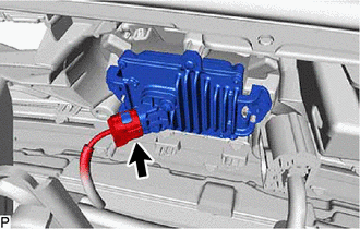
2. REMOVE MILLIMETER WAVE RADAR SENSOR ASSEMBLY
| (a) Disconnect the connector. |
|
(b) Remove the 2 bolts and screw.
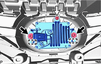
.png) |
Bolt |
.png) |
Screw |
(c) Disengage the 2 guides and remove the millimeter wave radar sensor assembly.
NOTICE:
Do not reuse the millimeter wave radar sensor assembly if it has been dropped or subjected to a severe impact.
READ NEXT:
 Installation
INSTALLATION PROCEDURE 1. INSTALL MILLIMETER WAVE RADAR SENSOR ASSEMBLY
NOTICE: If the millimeter wave radar sensor assembly has been struck or dropped, replace the millimeter wave radar sensor asse
Before Starting Driving Adjustment
BEFORE STARTING DRIVING ADJUSTMENT CAUTION / NOTICE / HINT
HINT:
Purpose of millimeter wave radar beam axis learning
If the installation position or orientation of the millimeter wave rada
Driving Adjustment
DRIVING ADJUSTMENT CAUTION / NOTICE / HINT
CAUTION: Radiofrequency radiation exposure information:
This equipment complies with FCC radiation exposure limits set forth for an uncontrolled envir
SEE MORE:
Components
COMPONENTS ILLUSTRATION
*1 FRONT FENDER APRON SEAL RH
*2 V-BANK COVER SUB-ASSEMBLY
N*m (kgf*cm, ft.*lbf): Specified torque
- - ILLUSTRATION
*1 CAMSHAFT TIMING GEAR BOLT
*2 O-RING
*3 CAMSHAFT TIMING OIL CONTROL SOLENOID ASSEM
Dtc Check / Clear
DTC CHECK / CLEAR CHECK FOR DTC (a) Check for DTCs (Test Failed / Pending / Confirmed). Chassis > Lane Control > Trouble Codes
Techstream Display Description
Test Failed Shows the malfunction judgment results during the current trip.
Pending Shows the malfunction ju
