Toyota Camry (XV70): Installation
INSTALLATION
PROCEDURE
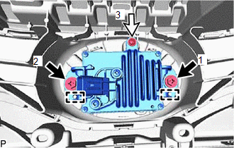
1. INSTALL MILLIMETER WAVE RADAR SENSOR ASSEMBLY
NOTICE:
If the millimeter wave radar sensor assembly has been struck or dropped, replace the millimeter wave radar sensor assembly with a new one.
(a) Engage the 2 guides.
.png) |
Bolt |
.png) |
Screw |
(b) Install the millimeter wave radar sensor assembly with the 2 bolts and screw.
Torque:
Bolt :
2.5 N·m {25 kgf·cm, 22 in·lbf}
HINT:
Tighten the bolts and screw in the order shown in the illustration.
(c) Connect the connector.
2. INSTALL COOL AIR INTAKE DUCT SEAL
Click here
.gif)
3. ADJUST MILLIMETER WAVE RADAR SENSOR
(a) When the millimeter wave radar sensor assembly is replaced with a new one, adjustment of the radar sensor beam axis must be performed.
HINT:
Millimeter wave radar sensor assembly learning can be performed by using either Target Adjustment (Triangle Target) or Target Adjustment (Flat Surface Target) or Driving Adjustment.
Target Adjustment (Triangle Target): Click here
Target Adjustment (Flat Surface Target): Click here
Driving Adjustment: Click here
READ NEXT:
 Before Starting Driving Adjustment
BEFORE STARTING DRIVING ADJUSTMENT CAUTION / NOTICE / HINT
HINT:
Purpose of millimeter wave radar beam axis learning
If the installation position or orientation of the millimeter wave rada
Driving Adjustment
DRIVING ADJUSTMENT CAUTION / NOTICE / HINT
CAUTION: Radiofrequency radiation exposure information:
This equipment complies with FCC radiation exposure limits set forth for an uncontrolled envir
Target Adjustment(triangle Target)
TARGET ADJUSTMENT(TRIANGLE TARGET) CAUTION / NOTICE / HINT
CAUTION: Radiofrequency radiation exposure information:
This equipment complies with FCC radiation exposure limits set forth for an un
SEE MORE:
Components
COMPONENTS ILLUSTRATION
*1 FRONT FENDER APRON SEAL RH
*2 V-BANK COVER SUB-ASSEMBLY
N*m (kgf*cm, ft.*lbf): Specified torque
- - ILLUSTRATION
*1 CAMSHAFT TIMING OIL CONTROL SOLENOID ASSEMBLY (for Intake Side of Bank 1)
*2 CAMSHAFT TIMIN
System Description
SYSTEM DESCRIPTION LUGGAGE COMPARTMENT DOOR OPENER SYSTEM DESCRIPTION
(a) If the luggage compartment door opening switch assembly is pressed and the luggage compartment door is closed, a luggage compartment door lock assembly open operation signal is sent to the main body ECU (multiplex network b
